Common Troubleshooting Issues with the LM5164DDAR
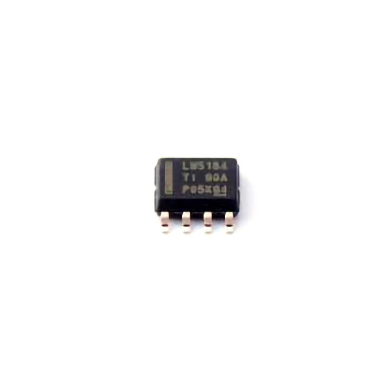
The LM5164DDAR is a high-performance, integrated, step-down (buck) voltage regulator designed to deliver stable and efficient power to a variety of applications. However, like any complex component, users may encounter issues during its implementation or operation. Whether you're designing a new circuit or diagnosing a malfunction in an existing system, knowing how to troubleshoot the LM5164DDAR can save time and ensure a reliable power supply.
1.1. Problem: No Output Voltage
One of the most common issues encountered with the LM5164DDAR is the lack of output voltage. The device might appear to be functioning but fails to provide the expected output.
Possible Causes:
Incorrect Feedback Network: The LM5164DDAR requires an appropriately designed feedback network to regulate the output voltage. If the feedback resistors are incorrectly placed or have the wrong values, the regulator may fail to produce the desired output.
Open Circuit or Faulty Components: Check for open circuits in the feedback loop, as this will prevent the regulation process.
Wrong Input Voltage: Ensure that the input voltage is within the operating range of the device. The LM5164DDAR requires an input voltage between 4.5V and 65V. If the input voltage is too low or too high, it may not be able to generate the correct output.
Solution:
Double-check the feedback resistors and their values to match the desired output voltage according to the datasheet.
Inspect the circuit for any open circuits or damaged components, especially around the feedback path.
Verify that the input voltage meets the specifications.
1.2. Problem: Excessive Ripple on Output
Another frequent issue with switching regulators like the LM5164DDAR is excessive ripple on the output voltage. Ripple refers to small, high-frequency fluctuations that superimpose on the DC output.
Possible Causes:
Inadequate Filtering: Insufficient output filtering can lead to ripple. The LM5164DDAR typically requires external capacitor s to smooth the output. If the capacitors are undersized or of poor quality, they may fail to filter out ripple effectively.
Inductor Issues: The quality and selection of the inductor used in the circuit also play a significant role in ripple. Using an inappropriate inductor can result in excessive ripple or noise.
PCB Layout Issues: Poor PCB layout can result in electromagnetic interference ( EMI ), which can manifest as ripple on the output. Long traces or improper grounding can act as antenna s and inject noise into the system.
Solution:
Ensure that the output capacitors meet the specifications in the datasheet and that they have low Equivalent Series Resistance (ESR) values.
Verify that the inductor is rated for the required current and has appropriate resistance values to minimize ripple.
Optimize the PCB layout by keeping traces as short and wide as possible, especially for high-current paths. Ensure a solid ground plane to minimize EMI and noise.
1.3. Problem: Overheating
Overheating is another common issue with voltage regulators. If the LM5164DDAR is running hotter than expected, it could lead to system instability and potential damage.
Possible Causes:
Excessive Load: An overly high load current can cause the regulator to overheat. The LM5164DDAR has a maximum output current of 3A, and any load that exceeds this can result in overheating.
Inadequate Heat Dissipation: Without proper thermal management, the regulator may not be able to dissipate heat efficiently. This can occur if the device is not mounted on a sufficiently large heat sink or if the PCB does not have adequate copper area for heat spreading.
Inefficient Components: Low-quality inductors or capacitors with high ESR values can increase power losses, leading to excessive heat generation.
Solution:
Ensure that the load current does not exceed the specified limits. Use a current-limiting device if necessary.
Implement good thermal design practices by increasing the copper area around the regulator for heat dissipation. Use a heatsink or thermal vias if required.
Choose low-ESR inductors and capacitors to reduce power losses and heat generation.
Advanced Troubleshooting and Solutions for the LM5164DDAR
Once basic troubleshooting has been carried out, you might encounter more subtle or advanced issues. These can sometimes be related to the design choices, component interactions, or operational conditions. In this section, we will discuss advanced solutions for more complex problems when using the LM5164DDAR.
2.1. Problem: Inconsistent Output Voltage Under Load
Under varying load conditions, you may notice that the output voltage from the LM5164DDAR is inconsistent or unstable, even when no obvious faults are present in the circuit.
Possible Causes:
Loop Stability Issues: The LM5164DDAR uses feedback to regulate its output. If the loop is unstable, the regulator may fail to respond correctly to changes in the load, causing output voltage fluctuations.
Poor Compensation Network: If the external compensation network is incorrectly designed, the system may experience poor transient response and instability.
Inadequate Load Regulation: A high source impedance in the power supply or issues with the regulator's current sensing circuitry can lead to poor load regulation.
Solution:
Review the compensation network, particularly the placement of resistors and capacitors in the feedback loop. The LM5164DDAR requires a specific set of components to ensure stable regulation, and incorrect choices can lead to instability.
Check for an appropriate output voltage ripple measurement under various loads to identify the problem's cause.
Consider using a more robust current sensing solution or improving the grounding and layout to enhance load regulation performance.
2.2. Problem: Unexpected Shutdown or Protection Mode
The LM5164DDAR includes built-in protection features like overvoltage, undervoltage, overcurrent, and thermal shutdown. Sometimes, these protective features may engage unexpectedly, causing the device to shut down.
Possible Causes:
Overcurrent Condition: If the load draws too much current, the regulator will enter an overcurrent protection mode to avoid damage. This can happen if the load current exceeds the maximum rated current or if the inductor is undersized.
Thermal Shutdown: Overheating due to insufficient heat dissipation or high ambient temperatures can cause the regulator to enter thermal shutdown mode.
Faulty Components or Short Circuits: A short circuit or damaged component on the output or input may trigger the protection circuitry.
Solution:
Verify that the load current does not exceed the maximum specified limits (3A for LM5164DDAR). If necessary, use a current-limiting circuit or a larger inductor to handle higher loads.
Improve thermal management by adding heatsinks or increasing PCB copper area to ensure the regulator stays within safe operating temperatures.
Inspect the entire circuit for any short circuits or component failures, particularly around the input and output pins.
2.3. Problem: Low Efficiency
One of the advantages of using a switching regulator like the LM5164DDAR is its efficiency. However, in some cases, users may experience lower-than-expected efficiency, leading to excessive heat and wasted power.
Possible Causes:
Incorrect Component Selection: Choosing components with suboptimal characteristics, such as high ESR capacitors or high-resistance inductors, can reduce efficiency.
Poor PCB Layout: Long, narrow traces can increase the resistance and lead to additional power losses. Additionally, poor grounding can increase EMI, affecting efficiency.
Wrong Switching Frequency: The switching frequency of the LM5164DDAR is adjustable, and incorrect settings could negatively impact efficiency. Lower switching frequencies might increase the size of the components, while higher frequencies might cause switching losses.
Solution:
Ensure that the capacitors and inductors are of high quality and meet the design specifications, particularly in terms of ESR and inductance.
Optimize the PCB layout to reduce resistance and EMI. Use wide, short traces for high-current paths and ensure proper grounding.
Adjust the switching frequency to an optimal value that balances efficiency and component sizes. This may require fine-tuning depending on the application.
In conclusion, troubleshooting the LM5164DDAR requires a methodical approach, addressing both basic and advanced issues. By carefully selecting components, optimizing the layout, and adhering to best design practices, users can ensure the reliable operation of this powerful step-down regulator. Keep in mind that thorough testing under different operational conditions is key to identifying and resolving problems effectively.
Partnering with an electronic components supplier sets your team up for success, ensuring the design, production, and procurement processes are quality and error-free.


