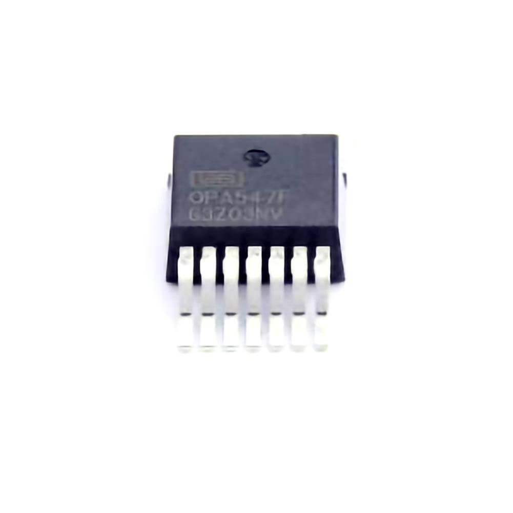
Understanding the OPA547F/500 Operational Amplifier
The OPA547F/500 is a high-performance, precision Power operational amplifier designed for use in a variety of applications, including motor control, Audio amplification, and industrial automation systems. Known for its high output current capability (up to 5A) and wide operating voltage range (±10V to ±40V), the OPA547F/500 is a powerful and versatile amplifier, but it does present a set of challenges that users should be aware of.
1. Key Features and Common Applications
The OPA547F/500 operational amplifier is a great choice for applications requiring both high current output and high precision. Key features include:
Output current up to 5A: This makes it suitable for driving low-impedance loads or providing significant current to power circuits.
Wide supply voltage range: The OPA547F/500 operates from ±10V to ±40V, providing flexibility in design.
Low distortion and high linearity: It is designed to minimize distortion, which is important in high-fidelity audio and other sensitive applications.
Thermal overload protection: The OPA547F/500 includes built-in thermal shutdown and short-circuit protection to safeguard the amplifier and prevent damage due to excessive heat or overcurrent conditions.
Applications typically include:
Audio power amplifiers
Motor drivers
Active filters
Instrumentation systems
Despite its robust features, users may face several challenges during the design, setup, or operation of OPA547F/500 circuits. Understanding the most common issues and how to troubleshoot them is essential for optimizing performance.
2. Common Troubleshooting Issues
Even though the OPA547F/500 is a reliable component, several issues might arise during its usage. Below are the most common problems users encounter:
2.1 Thermal Overload Shutdown
One of the primary concerns with high-power operational amplifiers is overheating, which can trigger the built-in thermal protection circuit to shut down the amplifier. When the chip reaches excessive temperatures, it stops functioning to prevent permanent damage.
Symptoms:
The amplifier suddenly stops working.
The output signal disappears or becomes distorted.
Possible Causes:
Inadequate heat sinking: The OPA547F/500 generates substantial heat, especially when driving large currents. Without proper heat dissipation (e.g., an appropriate heatsink), the amplifier may overheat.
Excessive load: The amplifier may be driving a load that requires more current than the OPA547F/500 can provide, leading to thermal stress.
Improper supply voltage: Excessive supply voltage can also increase power dissipation, leading to overheating.
Solutions:
Improve heat sinking: Ensure the amplifier is mounted on a sufficient heatsink. The OPA547F/500 requires a thermal resistance (junction-to-case) of 1°C/W to prevent overheating.
Reduce load: Check the load impedance and ensure it is within the operating limits of the amplifier. Avoid demanding too much current from the output stage.
Check the supply voltage: Ensure that the supply voltage is within the recommended range (±10V to ±40V). Exceeding these limits can lead to excessive power dissipation.
2.2 Output Clipping or Distortion
When the OPA547F/500 is driven beyond its maximum output capabilities, clipping or distortion can occur. This happens when the output voltage tries to exceed the supply voltage, resulting in a "flat-topped" or distorted waveform.
Symptoms:
The output signal is distorted, even at moderate signal levels.
The amplifier cannot reach the expected output voltage.
Possible Causes:
Excessive input signal: If the input signal is too large for the given supply voltage, the amplifier will try to drive the output beyond its maximum capability, causing clipping.
Incorrect feedback network: If the feedback network is improperly designed or implemented, the closed-loop gain could be too high, leading to saturation.
Solutions:
Limit the input signal: Ensure that the input signal does not drive the amplifier into saturation. Keep the signal within the acceptable range defined by the supply voltage.
Adjust the feedback network: Modify the feedback resistors to adjust the gain appropriately. This can help avoid excessive amplification of the input signal that leads to clipping.
2.3 Oscillations and Instability
Another common issue with the OPA547F/500 is instability, often manifested as oscillations or high-frequency noise. This problem typically occurs in feedback systems where improper layout or insufficient compensation can cause the amplifier to oscillate.
Symptoms:
The amplifier produces a high-frequency "whining" or "hissing" sound.
Oscillations appear in the output waveform even when the input signal is a clean DC or low-frequency sine wave.
Possible Causes:
Improper PCB layout: High-speed op-amps like the OPA547F/500 are sensitive to layout issues, such as long feedback loops, poorly placed decoupling capacitor s, or inadequate grounding.
Insufficient bypassing: If the power supply rails are not properly bypassed with appropriate capacitors, the amplifier can become unstable.
Too high gain-bandwidth: In some cases, a high gain-bandwidth product (GBW) could result in the amplifier being prone to oscillations when operating at high gains or low frequencies.
Solutions:
Improve PCB layout: Keep feedback loops short and direct, minimize the path between power supply pins and the bypass capacitors, and use proper grounding techniques.
Use proper bypassing: Place appropriate capacitors (e.g., 0.1µF ceramic capacitors) as close as possible to the power supply pins of the OPA547F/500.
Compensate for instability: If necessary, use external compensation to stabilize the amplifier, especially in high-gain configurations.
2.4 Output Offset and Drift
Some users may notice an offset voltage at the output of the OPA547F/500, which can result in inaccurate signal reproduction or unwanted DC shifts in the output waveform.
Symptoms:
The output has a constant DC offset.
The output voltage drifts over time.
Possible Causes:
Input bias current: Like most operational amplifiers, the OPA547F/500 has a small input bias current that can generate an offset voltage at the output if the input impedance is high.
Temperature variations: Temperature changes can affect the performance of the amplifier, causing the offset voltage to drift.
Improper zeroing: If the amplifier is not properly zeroed or calibrated, it may exhibit an initial offset voltage.
Solutions:
Use offset nulling: The OPA547F/500 has pins dedicated to offset nulling. Connect a potentiometer to these pins to adjust the output offset to zero.
Use a feedback resistor: In some cases, adding a feedback resistor to ground can help reduce offset voltage.
Temperature compensation: For more sensitive applications, consider adding temperature compensation circuits to minimize drift over a wide range of environmental conditions.
Advanced Troubleshooting and Optimization Techniques
While the common issues listed above are a good starting point for most OPA547F/500 troubleshooting efforts, some users may face more complex challenges in their designs. In this section, we will explore more advanced techniques for diagnosing and resolving these issues to ensure the OPA547F/500 performs at its best.
3. Advanced Troubleshooting Techniques
3.1 Power Supply Noise and Ripple
Noise or ripple in the power supply can have a significant impact on the performance of the OPA547F/500, especially in sensitive or high-precision applications. If the power supply is noisy, it can induce unwanted oscillations or distortions in the output signal.
Symptoms:
Noise or hum in audio applications.
Unwanted variations in the output signal.
Possible Causes:
Inadequate power supply filtering: The power supply may not be properly filtered, allowing high-frequency noise to couple into the amplifier.
Ground loop issues: Ground loops can introduce noise into the amplifier, leading to hum or oscillations.
Solutions:
Improve power supply filtering: Add additional bypass capacitors at both the power supply and amplifier pins. Consider using larger electrolytic capacitors for low-frequency filtering and ceramic capacitors for high-frequency noise suppression.
Use differential power supplies: If possible, use a dual differential power supply to help eliminate common-mode noise and ground loops.
Check grounding and shielding: Ensure that the ground plane is continuous and has a low impedance. Use shielding to isolate noisy components from sensitive parts of the circuit.
3.2 Overvoltage and Protection Circuits
In some applications, the OPA547F/500 may be exposed to voltage spikes or overvoltage conditions. These can occur due to inductive loads, switching transients, or improper circuit design. Overvoltage can damage the amplifier or cause it to malfunction.
Symptoms:
The amplifier stops working after a voltage spike.
Unpredictable behavior or erratic output.
Possible Causes:
Inductive kickback: Inductive loads (such as motors or solenoids) can generate high-voltage spikes when switched off.
Inadequate protection: The circuit may not have adequate overvoltage protection, leaving the OPA547F/500 vulnerable to spikes.
Solutions:
Add overvoltage protection: Use diodes, such as Schottky diodes, to clamp voltage spikes to safe levels. Zener diodes can also be used to limit voltage to a specific threshold.
Use snubber circuits: For inductive loads, use snubber circuits to absorb voltage spikes and protect the amplifier.
Implement fuses: A fuse or current-limiting resistor can be added to prevent excessive current from reaching the OPA547F/500 during transient events.
This concludes the first part of our in-depth troubleshooting guide for the OPA547F/500 operational amplifier. Stay tuned for Part 2, where we will explore more advanced solutions, real-world case studies, and tips for optimizing performance in various applications.
Partnering with an electronic components supplier sets your team up for success, ensuring the design, production, and procurement processes are quality and error-free.

