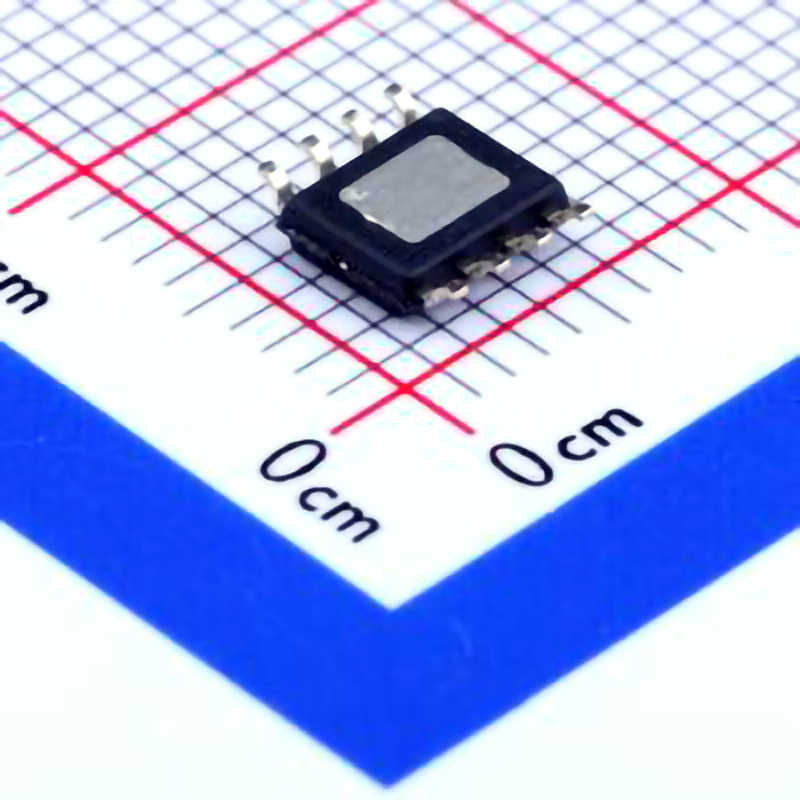
Introduction to the TPS5450DDA R and Common Issues
The TPS5450DDAR , a 60V, 5A step-down (buck) voltage regulator from Texas Instruments, has gained widespread popularity due to its high efficiency, compact size, and versatility in a wide range of applications. From industrial equipment to consumer electronics, this regulator is often used to convert high input voltages to stable, lower output voltages.
Despite its reliability, like any complex electronic component, the TPS5450DDAR can face issues that affect its performance. Understanding these potential problems and knowing how to troubleshoot them is essential for engineers and technicians who depend on this device for their power supply needs. In this first part, we'll cover the typical issues users might encounter when working with the TPS5450DDAR.
1. Incorrect Output Voltage
One of the most common issues when using the TPS5450DDAR is obtaining an incorrect output voltage. This can manifest as either a lower-than-expected or higher-than-expected output. Several factors could cause this discrepancy:
Feedback Loop Problems: The TPS5450DDAR relies on a feedback loop to regulate the output voltage. If there are issues with the feedback network, such as incorrect resistor values or poor soldering, the regulator may not properly sense the output voltage and adjust accordingly.
Faulty Compensation Network: The device uses a compensation network to ensure stability. Incorrect or out-of-spec components, such as the external capacitor s or resistors, can cause instability or improper voltage regulation.
Incorrect VIN or EN Pin Voltage: The input voltage (VIN) and enable pin (EN) need to be within specified limits for proper operation. If the input voltage is too low or the enable pin is not driven correctly, the output voltage will be affected.
Solution: Begin by checking the resistor values in the feedback loop and ensuring they match the recommended configuration for your desired output voltage. Ensure that the feedback capacitor is within spec and correctly placed on the board. Also, verify that the input voltage and enable pin voltages meet the specifications in the datasheet.
2. Excessive Heat Generation
Another common issue with the TPS5450DDAR is excessive heat generation. While the TPS5450 is designed to be efficient, high power dissipation can still occur under certain conditions. This typically results in thermal shutdown or a significant reduction in the regulator's efficiency.
Overcurrent or Short Circuit: If the output is overloaded or shorted, the regulator will experience excessive current flow, leading to higher-than-normal power dissipation.
Inadequate PCB Thermal Design: The efficiency of the regulator can be affected by poor PCB layout, insufficient copper area for heat dissipation, or improper placement of thermal vias.
Improper Output Capacitor: If the output capacitor is too small or does not have the proper ESR (equivalent series resistance), it can cause increased ripple and lead to more heat generation in the regulator.
Solution: Use a thermal camera to check for hot spots on the PCB and identify areas that may need more heat dissipation. Ensure that the PCB design includes proper copper planes for heat dissipation, and place sufficient thermal vias near the TPS5450DDAR. Additionally, confirm that the output capacitor is within the recommended specifications.
3. Output Voltage Ripple and Noise
Excessive ripple and noise at the output of the TPS5450DDAR can be detrimental to the performance of sensitive circuits, such as analog sensors or high-precision equipment. Ripple occurs due to the switching nature of the buck converter, but high ripple levels can be a sign of underlying issues.
Incorrect Output Capacitor Value: The output capacitor plays a crucial role in filtering high-frequency ripple. If the capacitor is too small or has an incorrect ESR, it can fail to adequately filter out noise and ripple.
Inadequate Input Capacitor: Similarly, insufficient input capacitance can cause input voltage fluctuations, which result in poor regulation and increased ripple at the output.
PCB Layout Issues: Poor PCB layout, such as long traces for the power and ground planes, can exacerbate noise and ripple problems.
Solution: Ensure that the input and output capacitors are selected according to the specifications in the datasheet. Pay attention to the ESR values and use low-ESR capacitors where required. Additionally, improve the PCB layout by minimizing the length of high-current traces and ensuring a solid ground plane to reduce noise and ripple.
4. Stability and Control Loop Issues
The TPS5450DDAR includes a control loop that helps maintain stable regulation across varying load conditions. If the control loop is not properly tuned or the components associated with it are faulty, the regulator may exhibit instability, causing oscillations or erratic behavior.
Compensation Network Failure: As mentioned previously, the external compensation network is critical for ensuring stability. An incorrect compensation network can cause instability at certain loads or input voltages.
Poor PCB Layout: A poor layout can also impact the performance of the control loop, especially in terms of noise coupling and feedback integrity.
Solution: Double-check the compensation network components and their placement on the PCB. Ensure that the values match those suggested for your specific application. Review the PCB layout to ensure that the feedback trace is short and away from noisy components or high-current paths.
Advanced Troubleshooting Techniques and Solutions for TPS5450DDAR
Now that we’ve covered the most common issues encountered with the TPS5450DDAR, let’s explore some advanced troubleshooting techniques and more detailed solutions. These advanced methods will help engineers and technicians diagnose deeper issues and ensure the TPS5450DDAR functions optimally.
5. Identifying and Solving Startup Failures
In some cases, the TPS5450DDAR may fail to start up properly, either not reaching the desired output voltage or failing to regulate at all. Startup issues can arise from various factors:
Enable Pin Issues: If the enable pin (EN) is not correctly driven high, the regulator will not initiate operation. A floating EN pin or incorrect voltage levels can prevent the TPS5450 from starting.
Undervoltage Lockout (UVLO): The TPS5450DDAR has a built-in undervoltage lockout feature to protect against low input voltages. If the input voltage drops below the UVLO threshold, the regulator will not operate.
Faulty External Components: A faulty external component, such as an inductor or capacitor, can cause issues during startup. If the inductor value is incorrect or if there are problems with the capacitors, the regulator may fail to start.
Solution: Start by checking the EN pin voltage to ensure it is properly driven high. If you are using external components, verify that the input voltage is above the UVLO threshold. Use an oscilloscope to monitor the voltage at the EN pin and the VIN pin during startup to ensure they meet the necessary levels.
6. Output Voltage Regulation Under Load Changes
The TPS5450DDAR is designed to regulate the output voltage across a range of load conditions. However, significant changes in load current may cause voltage deviations if the regulator cannot respond fast enough. This is particularly problematic in dynamic load applications where load current varies quickly.
Large Load Transients: Large, fast changes in load current can cause significant voltage dips or overshoot due to insufficient transient response.
Insufficient Output Capacitance: A low value or poor-quality output capacitor can degrade the regulator’s ability to maintain stable voltage under load changes.
Feedback Loop Saturation: If the feedback loop components are not properly selected or configured, the loop may not be able to respond quickly enough to maintain regulation during load transients.
Solution: Improve the transient response by increasing the output capacitance and selecting capacitors with low ESR. You can also adjust the compensation network to improve the response time of the feedback loop. Additionally, test under various load conditions to ensure the regulator can handle fast load transients.
7. Monitoring and Measuring Efficiency
Efficiency is a key performance metric for the TPS5450DDAR, and low efficiency can indicate underlying problems. If the regulator is not as efficient as expected, the system may dissipate excessive power as heat, which could lead to thermal shutdown or reduced system lifespan.
Excessive Input Current: If the input current is higher than expected for a given load, it may indicate a problem with the regulator’s internal circuitry or an issue with the external components.
High Switching Losses: The TPS5450DDAR uses high-frequency switching to convert power, and switching losses can increase if the component values are not optimized.
Faulty Components: A malfunctioning inductor or capacitor can increase losses and reduce efficiency.
Solution: Measure the input and output currents and compare them to the expected values. Check for any anomalies or excessive losses in the system. Ensure that the external components are within specification and optimized for efficiency. You can also use a thermal camera to detect hot spots, which may indicate areas of excessive power loss.
8. EMI and Noise Mitigation
Electromagnetic interference (EMI) and noise are common concerns in power supply designs, especially with high-speed switching regulators like the TPS5450DDAR. Excessive EMI can affect the performance of nearby sensitive electronics.
Layout and Grounding Issues: Poor grounding and layout can exacerbate EMI problems. Long traces, improper grounding, and inadequate shielding can cause noise to couple into other parts of the circuit.
Switching Frequency and Harmonics: The switching frequency of the TPS5450DDAR is high, and if not properly managed, it can radiate EMI. Harmonics from the switching process can also affect nearby circuits.
Solution: To reduce EMI, optimize the PCB layout by keeping high-current paths short and ensuring a solid ground plane. Use ceramic capacitors for filtering, and consider adding external EMI filters if necessary. Shielding the regulator or adding a ferrite bead to the input or output may also help mitigate noise.
By addressing these common and advanced troubleshooting issues, you can ensure that the TPS5450DDAR operates efficiently and reliably in your power supply designs. Whether you are dealing with startup failures, excessive ripple, heat generation, or load regulation issues, the solutions provided in this guide will help you troubleshoot and fix the problems effectively.
If you are looking for more information on commonly used Electronic Components Models or about Electronic Components Product Catalog datasheets, compile all purchasing and CAD information into one place.


