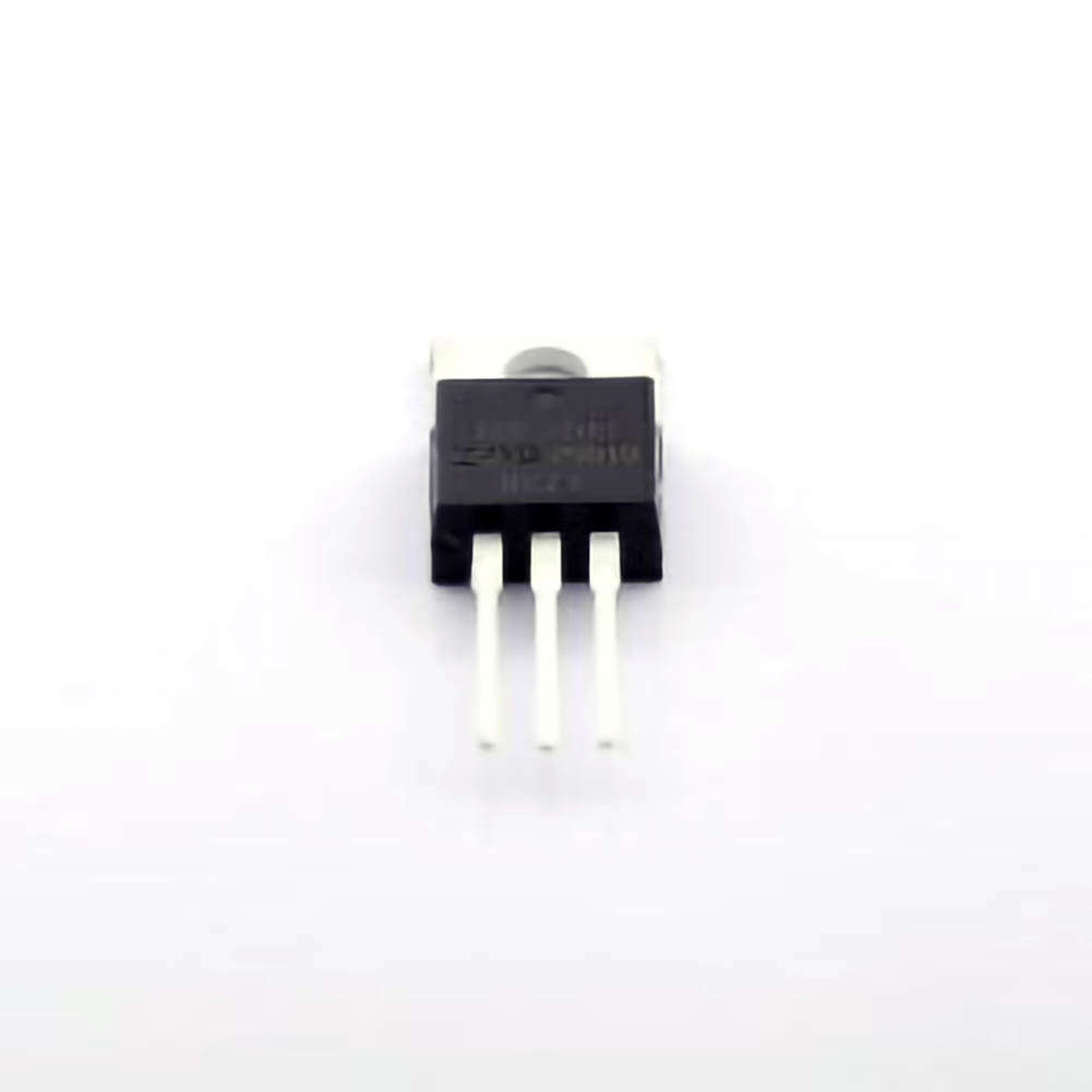
The IRF3205PBF is a widely used N-channel MOSFET known for its robust pe RF ormance in power electronics. However, like any electronic component, it can experience issues that may disrupt its performance. This article explores common troubleshooting techniques and solutions for the IRF3205 PBF, helping engineers and hobbyists address problems efficiently.
Introduction to the IRF3205PBF and Its Applications
The IRF3205PBF is a popular N-channel power MOSFET produced by International Rectifier, now part of Infineon Technologies. It is primarily used in power electronics applications, including motor control, switching power supplies, and high-frequency inverters. The MOSFET features low RDS(on), high current handling capacity (up to 55A), and low gate charge, making it an ideal choice for applications requiring efficient power switching.
Despite its advantages, like all electronic components, the IRF3205PBF is susceptible to faults, typically arising from improper handling, design errors, or environmental factors. Understanding common issues and troubleshooting solutions can significantly improve the reliability and longevity of your circuits.
Common Troubleshooting Issues with IRF3205PBF
When a circuit using the IRF3205PBF starts malfunctioning, it’s essential to diagnose the problem quickly to minimize downtime. Below are some of the most common issues users face when working with this MOSFET:
Overheating and Thermal Runaway
Thermal runaway occurs when the MOSFET heats up to the point where its ability to conduct current decreases, which further increases its temperature. This vicious cycle can lead to permanent damage to the IRF3205PBF if not managed properly. Overheating can be caused by improper heat sinking, excessive power dissipation, or high ambient temperatures.
Solution:
To resolve overheating issues, ensure proper heat sinking and thermal management in your design. Verify that the MOSFET is operating within its specified temperature range. Use thermal pads or heatsinks and ensure the circuit has proper airflow. If the circuit design allows for it, reduce the power dissipation by using a higher value of resistance for the current-limiting resistors or adjusting the duty cycle in PWM applications.
Gate Drive Issues (Low Gate Voltage)
The IRF3205PBF requires a sufficiently high gate voltage (Vgs) to switch on fully and reduce RDS(on). If the gate voltage is too low, the MOSFET will not enter saturation mode, resulting in excessive power dissipation, slower switching speeds, and potential failure. This issue can arise from incorrect gate driver circuitry or inadequate voltage supply.
Solution:
Verify that the gate driver is providing a voltage higher than the MOSFET’s threshold voltage (typically around 2-4V) and within the recommended Vgs range (±20V). If using a PWM signal, ensure the signal is clean and strong enough to drive the gate. Using a dedicated MOSFET driver IC or a dedicated gate driver transistor can help improve switching efficiency.
Incorrect Circuit Design (Improper Use in Low-Side or High-Side Switches )
The IRF3205PBF is most effective when used in low-side switching configurations, but some designs mistakenly use it in high-side switching circuits. This can lead to improper operation due to the need for proper gate drive voltage above the source terminal.
Solution:
Always use the IRF3205PBF in low-side switching configurations unless your circuit design specifically incorporates a bootstrap driver for high-side switching. For high-side switching, consider using a P-channel MOSFET or a dedicated high-side MOSFET driver.
Damaged or Shorted MOSFET
A common problem that can arise from overstress conditions, such as excessive voltage or current, is a damaged MOSFET. If the MOSFET is subjected to voltage spikes, improper handling, or excessive current, it could short internally, causing permanent failure.
Solution:
The first step is to check the MOSFET for signs of damage, such as visible burn marks, cracks, or bulging. If the MOSFET appears damaged, replace it with a new one. Ensure that your circuit is protected with components like diodes or TVS (Transient Voltage Suppressors) to prevent voltage spikes from damaging the MOSFET in the future. A current-limiting feature or fuse can also help prevent overcurrent issues.
Gate-Source Leakage
Gate-source leakage occurs when an unintended current flows between the gate and the source terminal. This leakage can result from insufficient insulation, high temperature, or a damaged MOSFET. Although the IRF3205PBF is designed to have minimal gate-source leakage, certain conditions can cause this issue.
Solution:
Measure the gate-source voltage and the leakage current to confirm if gate-source leakage is occurring. If leakage is present, check for damage to the MOSFET or inadequate insulation. Consider replacing the damaged MOSFET and ensure that the circuit's operating environment remains within the manufacturer's recommended temperature range.
Advanced Troubleshooting Techniques for IRF3205PBF
While the basic troubleshooting solutions mentioned in Part 1 cover many common issues, there are more advanced diagnostic steps that can be taken when problems persist. These techniques require more in-depth knowledge of circuit analysis and testing.
Oscilloscope Analysis for Switching Issues
If your IRF3205PBF is not switching correctly, or if there is significant switching noise or ringing, an oscilloscope is an invaluable tool. By monitoring the gate voltage and drain-source voltage waveforms, you can determine if the MOSFET is switching fully and quickly or if there are delays or partial switching events.
Solution:
Use the oscilloscope to inspect the gate drive signal. Ensure that it is sharp, well-defined, and matches the expected voltage levels. If you observe slow or oscillatory switching behavior, check for issues such as parasitic inductance or capacitance, a lack of proper decoupling capacitor s, or a poorly designed gate driver. To reduce ringing, consider adding a gate resistor or improving the layout to minimize parasitic elements.
Using a Multimeter to Check for Continuity
A quick and effective method to check for basic MOSFET failures is to use a multimeter to test for continuity between the drain, source, and gate terminals when the power is off. In a properly functioning MOSFET, you should see a very high resistance between the drain and source in the off state and a low resistance when the MOSFET is on (with the gate appropriately biased).
Solution:
If you find a short circuit between the drain and source or between the gate and source when the MOSFET is not supposed to be conducting, it indicates that the MOSFET has likely failed. Replace it with a new component. You can also check the gate for any leakage currents by measuring the voltage with the gate disconnected.
Verifying External Components and Protection Circuits
In many cases, issues related to the IRF3205PBF may not stem from the MOSFET itself, but from the surrounding circuitry. External components like resistors, capacitors, and diodes can affect the operation of the MOSFET. For example, a damaged flyback diode could cause voltage spikes that damage the MOSFET, or an improperly sized gate resistor could slow down switching times, leading to inefficiency and heating.
Solution:
Check all surrounding components, especially passive components, for signs of wear, failure, or improper ratings. Ensure that your flyback diodes are rated for the appropriate voltage and current, and verify that any gate resistors are chosen to balance switching speed and noise reduction. Additionally, ensure that decoupling capacitors are properly placed near the power supply pins to filter high-frequency noise.
Simulating the Circuit with SPICE Models
Before making physical repairs, you can simulate the circuit using SPICE (Simulation Program with Integrated Circuit Emphasis) tools. Many manufacturers, including Infineon, provide SPICE models for components like the IRF3205PBF. This allows you to test the circuit behavior under different conditions and pinpoint potential problems before making hardware changes.
Solution:
Download the IRF3205PBF SPICE model from the manufacturer’s website or other reliable sources, and simulate the circuit using a tool like LTspice. Adjust parameters such as gate voltage, load resistance, and ambient temperature to see how they affect the operation of the MOSFET. This can help you predict how the MOSFET will behave in a real-world scenario, allowing you to optimize your design.
Conclusion
The IRF3205PBF is an excellent choice for high-power switching applications due to its low on-resistance and high current capacity. However, as with any electronic component, it requires careful handling and proper circuit design to ensure reliability. By following the troubleshooting steps outlined in this article, you can address common issues such as overheating, gate drive problems, and circuit design errors. For more complex problems, advanced techniques like oscilloscope analysis, multimeter continuity checks, and SPICE simulations can help you identify and resolve the issue effectively.
By keeping these solutions in mind and adhering to best practices for circuit design and component handling, you can maximize the performance and lifespan of the IRF3205PBF MOSFET in your power electronics projects.
Partnering with an electronic components supplier sets your team up for success, ensuring the design, production, and procurement processes are quality and error-free.


