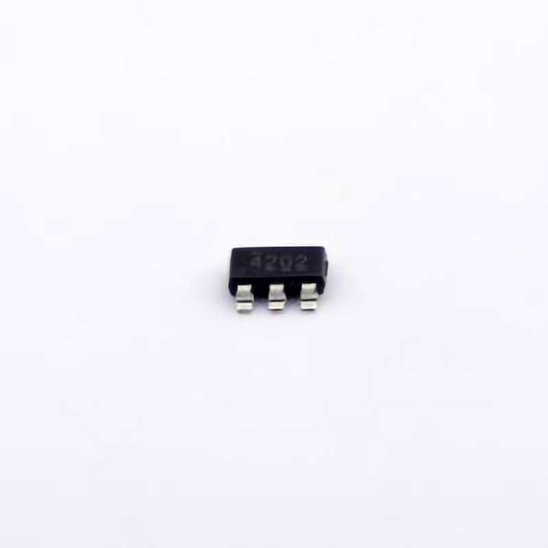
The MMBT3904 LT1G is a versatile NPN transistor commonly used in electronic circuits for signal amplification, switching, and other essential functions. However, like any electronic component, it can present various issues that may hinder performance. This article explores common troubleshooting steps and solutions for addressing problems that may arise when working with the MMBT3904LT1G transistor.
MMBT3904LT1G, NPN transistor, troubleshooting, electronic components, signal amplification, switching, common issues, transistor failure, circuit design, electronic repair, component solutions
Common Troubleshooting Issues with MMBT3904LT1G Transistor
The MMBT3904LT1G is a popular NPN transistor that finds widespread use in low- Power applications such as signal amplification, switching, and driving circuits. Its robustness and versatility make it a go-to choice for engineers and hobbyists alike. However, as with any electronic component, the MMBT3904LT1G is not immune to issues. Understanding common problems and knowing how to resolve them is essential for smooth circuit operation and design.
1.1 Incorrect Transistor Biasing
One of the most frequent issues encountered with the MMBT3904LT1G is improper biasing, which affects the transistor's performance. In order for a transistor to function as intended, its base, collector, and emitter must be properly biased to ensure it operates in the correct region (active, saturation, or cut-off).
Symptoms of Incorrect Biasing:
The transistor might not switch on or off correctly.
It may produce distorted output signals or fail to amplify.
The transistor could become overly hot or even damaged.
Solutions:
Base Resistor Calculation: Ensure that the base resistor is properly sized. Use Ohm’s Law to calculate the correct base current (Ib). The base current should be sufficient to drive the transistor into its active region but not too large to cause excessive power dissipation.
Proper Voltage Levels: Verify that the voltage levels at the base, collector, and emitter are within the recommended operating ranges (base-emitter voltage should typically be around 0.7V for silicon transistors like the MMBT3904LT1G).
Use of Voltage Dividers : In circuits where more precise biasing is required, using a voltage divider for the base can help ensure consistent and stable operation.
1.2 Overheating of the Transistor
Overheating is a serious issue that can lead to transistor failure. If the MMBT3904LT1G gets too hot, it can suffer from thermal runaway, which may permanently damage the transistor or degrade its performance.
Symptoms of Overheating:
The transistor feels hot to the touch.
The circuit may malfunction, especially under load conditions.
A noticeable drop in gain or signal output may occur.
Solutions:
Heat Dissipation: Ensure adequate heat dissipation by placing the transistor in a well-ventilated area or using heat sinks for higher power applications. Even though the MMBT3904LT1G is a low-power transistor, it can still heat up under certain conditions, especially if driven too hard.
Current Limiting: Use Resistors in series with the collector to limit the current and reduce the chances of excessive heating. It’s important to ensure that the collector current (Ic) does not exceed the specified maximum rating.
Thermal Management : Implement thermal management strategies such as PCB layout optimization, ensuring the transistor is not surrounded by heat-sensitive components. Proper grounding and trace thickness are crucial for heat dissipation.
1.3 Transistor Failure Due to Excessive Collector-Emitter Voltage
The MMBT3904LT1G has specific limits on its collector-emitter voltage (Vce). If this voltage exceeds the rated value, the transistor can become damaged, often resulting in permanent failure. In many cases, this is due to a mismatch between the operating voltage in the circuit and the transistor’s specifications.
Symptoms of Excessive Vce:
The transistor fails to turn on or off.
Circuit functionality is inconsistent.
A burnt smell or visible damage to the transistor may occur.
Solutions:
Voltage Clamping: Use a zener diode or other clamping components to limit the Vce. A zener diode with a breakdown voltage near the transistor’s maximum Vce can protect the transistor from excessive voltage.
Circuit Protection : In high-voltage applications, consider adding over-voltage protection or using transistors with higher voltage ratings (such as the MMBT2222 or other higher-rated devices).
Voltage Rating Awareness: Always check the maximum Vce rating of the MMBT3904LT1G (40V) and design your circuit accordingly to avoid exceeding this threshold.
1.4 Signal Distortion Due to Low Gain or Saturation
In certain configurations, the MMBT3904LT1G may exhibit reduced gain or cause signal distortion. This is often due to the transistor being driven into saturation (when both the base-emitter and collector-emitter junctions are forward biased), causing the transistor to behave more like a switch than an amplifier.
Symptoms of Signal Distortion:
The output signal is clipped or square-wave-like, particularly in amplifier circuits.
The transistor fails to produce a smooth, amplified signal.
The circuit operates as an on/off switch rather than a variable signal processor.
Solutions:
Avoid Saturation: Ensure the base current is not excessive, which could force the transistor into saturation. Carefully adjust the base resistor to allow for linear operation in the active region.
Feedback Resistors: In amplifier circuits, use feedback resistors to control the gain and maintain the transistor’s operation in the active region. This helps avoid distortion by ensuring the transistor operates in its linear region.
Additional Troubleshooting and Best Practices for MMBT3904LT1G Transistors
While common issues such as improper biasing, overheating, excessive Vce, and signal distortion can affect the MMBT3904LT1G’s performance, further troubleshooting techniques and best practices can help mitigate these problems and ensure more reliable operation.
2.1 Ensuring Proper Transistor Orientation
Incorrect transistor orientation is a simple but often overlooked issue that can cause malfunction. The MMBT3904LT1G, like other transistors, has three terminals: base (B), collector (C), and emitter (E). If these terminals are incorrectly connected in the circuit, the transistor will not function as intended.
Symptoms of Incorrect Orientation:
No amplification or switching functionality.
The circuit behaves erratically or produces incorrect output signals.
In some cases, the transistor may overheat or be damaged due to improper current flow.
Solutions:
Double-Check Pinout: Always double-check the datasheet for the correct pinout of the MMBT3904LT1G. For the MMBT3904LT1G, the typical pinout is: pin 1 – emitter (E), pin 2 – base (B), and pin 3 – collector (C).
Correct PCB Design: Ensure that the PCB layout correctly reflects the transistor’s pinout. Using proper labeling and design tools will help avoid orientation issues.
Visual Inspection: During assembly, visually inspect the placement of the transistor to confirm the correct orientation before powering up the circuit.
2.2 Ensuring Clean and Stable Power Supply
A noisy or unstable power supply can cause erratic behavior in the MMBT3904LT1G, particularly in analog applications. Power supply fluctuations can lead to incorrect biasing or even cause the transistor to operate outside its intended range.
Symptoms of Power Supply Issues:
The circuit exhibits intermittent performance or does not work at all.
There is visible noise in the output signal (e.g., hum or jitter).
The transistor may fail to amplify or switch as expected.
Solutions:
Use Decoupling capacitor s: Place decoupling Capacitors near the power supply pins of the transistor to filter out high-frequency noise and smooth the power supply. Capacitors in the range of 10nF to 100nF are commonly used for this purpose.
Stabilize Power Rails: Ensure the power supply is well-regulated and within the required voltage range for the MMBT3904LT1G. For example, ensure that the Vcc does not exceed the maximum rated voltage of the transistor.
Grounding Considerations: Proper grounding is critical for maintaining stability in analog circuits. Make sure that the ground connections are solid, and there is no ground loop causing interference.
2.3 Preventing ESD Damage
Electrostatic discharge (ESD) can be a significant concern for sensitive components like the MMBT3904LT1G. ESD can damage the transistor permanently, even if no visible signs of damage are observed.
Symptoms of ESD Damage:
Transistor fails to function immediately after installation.
Circuit experiences intermittent failures or erratic behavior.
Visible damage (such as a burnt or cracked package) may not always be apparent.
Solutions:
Use ESD Protection: Always handle the MMBT3904LT1G in an ESD-safe environment. Use anti-static wrist straps, mats, and bags to prevent electrostatic buildup.
ESD-Proof Socket s: When testing or experimenting with transistors, use ESD-proof sockets or fixtures to minimize the risk of damage during insertion and removal.
Proper Storage: Store unused transistors in anti-static bags to protect them from potential damage while not in use.
2.4 Testing and Measuring Performance
For precise troubleshooting, using appropriate tools to test the transistor’s parameters is essential. Multimeters, oscilloscopes, and transistor testers are invaluable when diagnosing issues with the MMBT3904LT1G.
Symptoms of Faulty Transistor:
Transistor does not perform within expected parameters.
Circuit output does not match the input signal characteristics.
Solutions:
Measure HFE (Gain): Use a multimeter or transistor tester to measure the transistor’s gain (hFE). If the gain is too low, the transistor may be faulty.
Check Junctions: Use a diode test function on your multimeter to check for shorts or open junctions between the base, collector, and emitter. A healthy MMBT3904LT1G will show a forward voltage drop of approximately 0.7V between the base and emitter when conducting.
In conclusion, the MMBT3904LT1G is a highly reliable and versatile NPN transistor, but like any electronic component, it is prone to certain issues that can compromise circuit functionality. By carefully understanding and addressing common troubleshooting problems, you can ensure that your circuits perform optimally and avoid unnecessary repairs or replacements. Whether you're designing simple signal amplifiers or more complex switching circuits, proper handling, biasing, and testing will lead to more successful and reliable use of this valuable component.
Partnering with an electronic components supplier sets your team up for success, ensuring the design, production, and procurement processes are quality and error-free.


