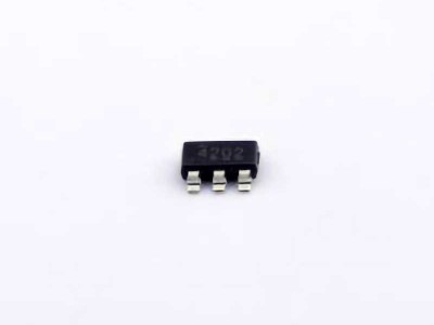
The TPS54202DDCR is a popular and reliable switching regulator from Texas Instruments, designed to meet the needs of various Power management applications. However, like any advanced electronic component, users may encounter challenges during its implementation. In this guide, we’ll explore common troubleshooting techniques and provide effective solutions to ensure optimal performance and longevity of your TPS54202DDCR. Whether you're a novice or experienced engineer, this article will help you resolve issues and improve the reliability of your designs.
TPS54202DDCR, troubleshooting, solutions, Texas Instruments, power management, DC-DC converters, switching regulator, voltage regulation, power supply, electronics troubleshooting.
Understanding the TPS54202DDCR and Common Issues
The TPS54202DDCR is a highly efficient step-down (buck) DC-DC converter designed to deliver a regulated output voltage for various applications. It operates at a wide input voltage range and is capable of producing a stable output, which is essential in powering modern electronic devices. However, due to its complexity and high integration, several factors could affect its performance, especially during the initial stages of design or integration into a system.
1. Overview of the TPS54202DDCR
Before diving into troubleshooting, it's important to have a clear understanding of the TPS54202DDCR’s key features:
Input Voltage Range: 4.5V to 60V.
Output Voltage Range: 0.8V to 5.5V (adjustable via external feedback resistor network).
Maximum Output Current: 2A.
Efficiency: Up to 96%, depending on load and input conditions.
Control Mode: Pulse-width modulation (PWM), which ensures excellent dynamic response and low output ripple.
The TPS54202DDCR is primarily used in applications where high efficiency and robust power management are essential, such as industrial control systems, automotive electronics, and battery-powered devices. While it is designed for ease of use with a simple external component requirement, users may still face challenges when integrating it into complex circuits.
2. Common Problems and Their Causes
Let’s discuss some of the most common issues encountered during the use of the TPS54202DDCR.
2.1 Output Voltage Instability or Ripple
One of the primary concerns with any DC-DC converter is output voltage instability or excessive ripple. While the TPS54202DDCR is designed for low ripple operation, users might experience noise or oscillations in the output under certain conditions.
Cause: Poor layout design or improper selection of external components (such as capacitor s and inductors) can lead to excessive ripple. For example, using capacitors with insufficient voltage ratings, or placing them too far from the IC, can reduce the effectiveness of the filtering stage.
Solution: Ensure that the layout is optimized for low noise. Keep the input and output capacitors as close to the IC as possible, and use high-quality low ESR (equivalent series resistance) capacitors. Additionally, check the inductor specifications, as choosing an incorrect inductor could cause instability in the switching regulator.
2.2 Overheating and Thermal Shutdown
Another common issue with high-performance power management ICs like the TPS54202DDCR is overheating. When the device exceeds its thermal limits, it may enter thermal shutdown mode to prevent damage.
Cause: Excessive input voltage, heavy load conditions, or insufficient cooling can cause the IC to overheat. A poorly designed thermal solution, such as inadequate PCB copper area or lack of a heatsink, can also lead to overheating.
Solution: Ensure that the input voltage is within the specified range and that the load does not exceed the rated current of 2A. Also, verify the PCB design, ensuring adequate copper area for heat dissipation. Consider adding a heatsink or improving airflow if necessary to keep the device within safe operating temperatures.
2.3 Inconsistent Start-Up or Failure to Power Up
When the TPS54202DDCR fails to power up or exhibits inconsistent start-up behavior, it can significantly disrupt the operation of the entire circuit.
Cause: A common cause of this issue is incorrect feedback network configuration, improper soft-start component selection, or issues with the input power supply.
Solution: Double-check the feedback resistor network and ensure it is properly configured for the desired output voltage. Also, verify that the input power supply is stable and within the correct voltage range. If using external components like a soft-start capacitor, make sure the component values align with the recommended specifications in the datasheet.
2.4 Output Voltage Not Reaching the Desired Level
The TPS54202DDCR is designed to provide a precise output voltage based on an external resistor divider network. If the output voltage deviates from the desired level, it could be due to several reasons.
Cause: Incorrect resistor values in the feedback network, or a damaged feedback pin, can result in inaccurate output voltage.
Solution: Check the resistor values in the feedback loop and verify that they are chosen according to the datasheet recommendations for the desired output voltage. Also, ensure that the feedback pin is not damaged and is properly connected to the output voltage sensing circuit.
3. Basic Troubleshooting Steps
When you encounter any issues with the TPS54202DDCR, follow these basic troubleshooting steps:
Check Component Selection: Ensure that all external components, such as inductors and capacitors, are properly selected based on the recommendations in the datasheet.
Inspect the Layout: Poor PCB layout can cause noise, instability, and overheating. Ensure that the IC is properly grounded and that power traces are thick enough to handle the current.
Verify Input Voltage: Measure the input voltage to confirm that it is within the recommended range (4.5V to 60V).
Check Output Voltage: Measure the output voltage and compare it to the expected level. If there’s a discrepancy, inspect the feedback network.
Monitor Temperature: Use an infrared thermometer or thermal camera to monitor the temperature of the IC during operation. If the IC is overheating, improve the thermal management system.
By following these steps, you can quickly identify the root cause of common issues and take appropriate corrective actions.
Advanced Troubleshooting and Best Practices for Reliable Operation
While the basic troubleshooting steps outlined above can resolve many common issues, some more complex problems require advanced techniques to diagnose and address. In this part of the article, we’ll delve deeper into advanced troubleshooting strategies and provide best practices for achieving reliable, long-term operation of the TPS54202DDCR.
4. Advanced Troubleshooting Techniques
4.1 Analyzing Switching Waveforms
For more complex issues such as voltage instability or ripple, analyzing the switching waveforms can provide valuable insights. Using an oscilloscope, observe the switching node (SW pin) and the output voltage waveform. This can help you identify whether the issue is related to switching noise, improper switching frequency, or problems with the phase of the switching signal.
Cause: If the switching waveform is not clean or has significant distortion, this could indicate issues with the inductor, capacitors, or the IC itself.
Solution: Check the inductor and capacitors for proper ratings and values. A poorly chosen inductor can cause excessive ripple or instability. Similarly, low-quality capacitors with high ESR can reduce the effectiveness of the output filter and lead to higher ripple.
4.2 Analyzing Load Transients
The TPS54202DDCR is designed to respond quickly to load transients, but if the response is poor or there’s significant overshoot, this could indicate a problem.
Cause: Inadequate output capacitors or a poorly chosen inductor could lead to a sluggish or over-compensated response to sudden load changes.
Solution: Improve the quality and capacitance of the output capacitors. Additionally, review the inductor choice to ensure it is optimized for the specific load and frequency conditions.
4.3 Input Voltage Drop and Power Supply Issues
A drop in input voltage can often cause instability or improper functioning of the TPS54202DDCR, especially under heavy load conditions. If the input voltage is sagging, it may not be able to supply the required current, especially if the input source is a battery or a poorly regulated supply.
Cause: A weak or poorly regulated input supply can lead to voltage dips, resulting in improper operation of the converter.
Solution: Measure the input voltage directly at the TPS54202DDCR input pin to verify if the voltage is stable. If you're using a battery, ensure that it is fully charged or capable of providing the required current. In cases of poor regulation, consider using a more stable input power source.
5. Best Practices for Reliable Operation
5.1 PCB Layout Best Practices
The layout of the PCB is crucial for ensuring the reliable performance of the TPS54202DDCR. Follow these layout guidelines to minimize noise, improve thermal dissipation, and reduce the risk of instability:
Keep the input and output capacitors as close to the IC as possible.
Use thick copper traces for power lines to minimize voltage drops and resistive losses.
Implement ground planes to provide low-impedance paths for return currents and reduce EMI .
Place a solid thermal pad under the IC for better heat dissipation.
5.2 Use of Proper Filtering
Adding proper filtering to the input and output can reduce noise and improve the overall performance of the converter. In particular, using low-ESR capacitors at both the input and output stages will help smooth voltage fluctuations and improve efficiency.
5.3 Temperature Monitoring
Thermal management is critical for the TPS54202DDCR’s reliability. Use temperature sensors or thermal cameras to monitor the operating temperature of the IC. Make sure that the IC does not exceed its maximum junction temperature.
5.4 Component Selection and Quality Control
Ensure that all components used in the power supply are of high quality and meet the required specifications. For instance, capacitors with high ESR or inductors with low current ratings could compromise performance. Use only high-quality components from reputable manufacturers to ensure long-term reliability.
Conclusion
The TPS54202DDCR is a highly capable and efficient power management solution for a wide range of applications, but like any sophisticated IC, it requires careful consideration during design and troubleshooting. By following the troubleshooting techniques outlined above, you can address most common issues that arise during the implementation of the TPS54202DDCR in your circuits. Additionally, adopting best practices in layout, component selection, and thermal management will help ensure reliable and long-lasting performance. Whether you're designing a new product or troubleshooting an existing system, understanding these key principles will set you up for success.
If you are looking for more information on commonly used Electronic Components Models or about Electronic Components Product Catalog datasheets, compile all purchasing and CAD information into one place.