Common Troubleshooting Issues with STM32F103 CBT6
Introduction
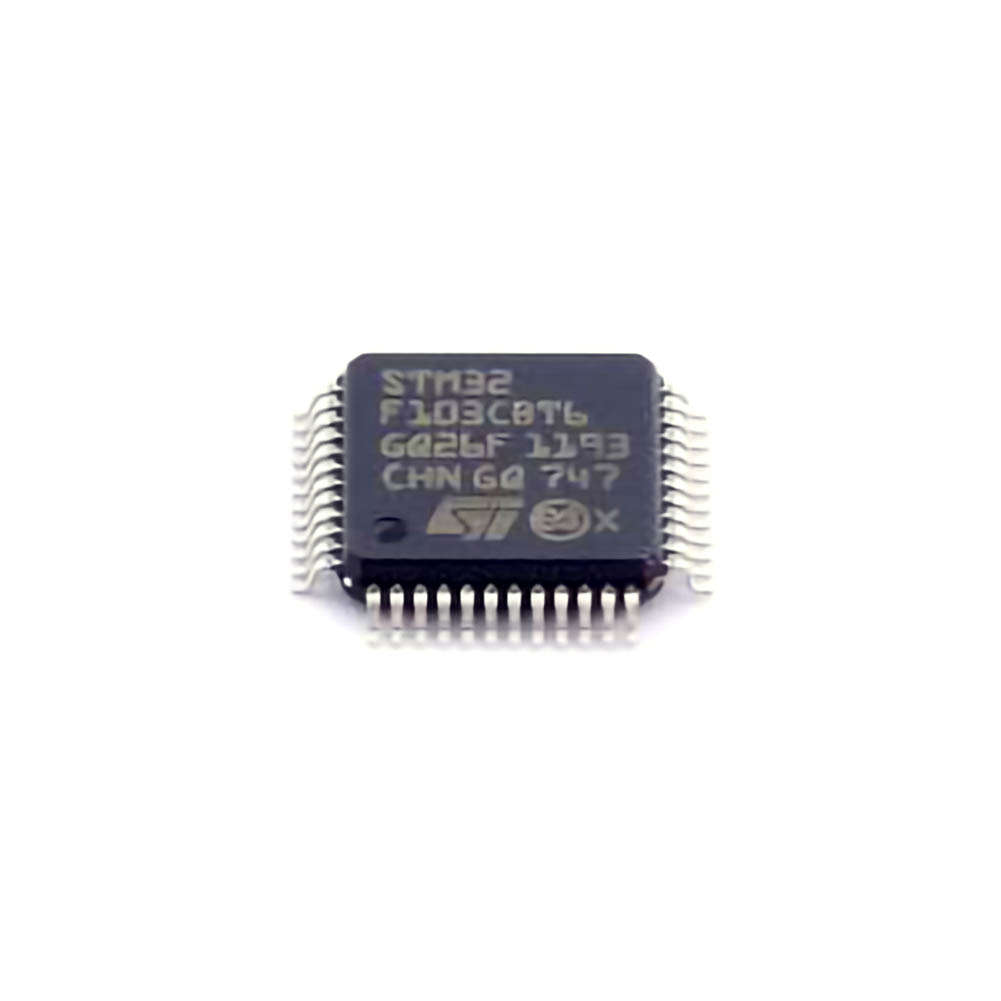
The STM32F103CBT6 is a Power ful and versatile microcontroller from the STM32 family, widely used in embedded systems, automation, and control applications. However, even with its popularity, users often face issues ranging from boot problems to peripheral malfunctions. Understanding these common problems and knowing how to troubleshoot them efficiently is crucial for maintaining the reliability and performance of your project.
In this section, we’ll explore some of the most common troubleshooting problems users encounter with the STM32F103CBT6, as well as provide practical solutions to resolve them.
1. Power Supply Issues
Symptoms:
The microcontroller does not start up or powers down unexpectedly.
The device may reset frequently or enter an unknown state during operation.
Causes:
Insufficient Power Supply: The STM32F103CBT6 operates at a 3.3V voltage level, and any variation in the supplied voltage can lead to operational failures.
Power Noise: Voltage spikes or dips caused by external components (such as motors or inductive loads) can cause the microcontroller to behave erratically.
Solutions:
Ensure that the power supply provides a stable 3.3V. A regulated power supply is essential for the STM32F103CBT6 to function correctly.
Use decoupling capacitor s (e.g., 100nF and 10uF) near the power supply pins to reduce power noise and stabilize the voltage.
If external components like motors or other high-power devices are used, implement proper filtering and protection circuits, such as diodes and capacitors, to mitigate noise.
Consider using a dedicated voltage regulator if your system is powered by an unregulated source.
2. Boot Failures and JTAG Debugging Issues
Symptoms:
The microcontroller fails to boot or load the firmware correctly.
JTAG or SWD (Serial Wire Debug) Communication fails to connect or is unreliable.
Causes:
Incorrect Boot Configuration: The STM32F103CBT6 has multiple boot modes (e.g., from Flash, from System Memory , or from RAM). If the Boot0 pin is incorrectly configured, the microcontroller may fail to boot from the correct source.
JTAG/SWD Configuration Problems: Incorrect configuration of the JTAG/SWD interface , or faulty connections, can prevent successful communication with the debugger.
Solutions:
Double-check the state of the Boot0 pin. When Boot0 is low, the microcontroller will boot from Flash memory; when high, it will boot from System Memory (where the built-in bootloader resides).
If you are using an external debugger, ensure that all pins are properly connected and that the voltage levels are correct. The JTAG interface requires stable communication between the debugger and the target device.
For successful JTAG debugging, confirm that the SWD or JTAG interface is correctly configured in your IDE (e.g., STM32CubeIDE or KEIL) and that the correct target device is selected.
3. Firmware Upload Failures
Symptoms:
The firmware fails to upload to the microcontroller.
The microcontroller appears to be "bricked" or unresponsive after attempting a firmware upload.
Causes:
Incorrect Boot Mode: If the Boot0 pin is set to boot from system memory (the built-in bootloader), the microcontroller may not allow a firmware upload unless the correct procedure is followed.
Corrupted Firmware or Flash: A failed or interrupted firmware upload can corrupt the microcontroller’s flash memory, preventing further uploads.
Solutions:
Ensure that Boot0 is set to low (0) when uploading firmware via ST-Link or any other in-system programmer. If Boot0 is high, you may need to use the bootloader via USART, USB, or other communication protocols.
If you suspect the firmware is corrupted, try performing a full erase of the flash memory before uploading a new firmware version. Use the ST-Link utility or STM32CubeProgrammer for this task.
Double-check the communication between your development environment and the microcontroller. Make sure your ST-Link or other programmer is properly configured and connected.
4. Peripheral Malfunctions (GPIO, ADC, UART, etc.)
Symptoms:
Digital inputs/outputs (GPIO) fail to operate as expected.
Analog-to-digital conversion (ADC) readings are incorrect or noisy.
UART communication fails or is unreliable.
Causes:
Improper Pin Configuration: Incorrect configuration of the GPIO pins (input vs. output, pull-up/down resistors) can lead to unexpected behavior.
Incorrect Clock Settings: Peripherals like UART, ADC, and timers depend on accurate clock settings. A misconfigured clock can prevent these peripherals from working correctly.
Signal Integrity Issues: Long wires or improper PCB layout can result in signal degradation, particularly for analog signals like those from the ADC.
Solutions:
Double-check the configuration of GPIO pins using STM32CubeMX or your chosen IDE. Ensure you have selected the correct mode for each pin (input, output, analog, etc.) and set the appropriate pull-up or pull-down resistors.
Verify the clock settings for your peripherals. For example, ensure the ADC clock is configured properly to avoid incorrect sampling rates.
When working with UART, check baud rates, stop bits, and parity settings. Ensure that both the transmitter and receiver devices are configured identically.
If you are facing issues with the ADC, reduce noise by adding filtering capacitors and ensuring proper grounding techniques.
For UART issues, use a logic analyzer or oscilloscope to monitor the signals and verify that the data is being transmitted and received as expected.
Advanced Troubleshooting Techniques and Solutions for STM32F103CBT6
5. Clock Configuration Issues
Symptoms:
The microcontroller fails to start or exhibits erratic behavior.
Peripherals like UART, timers, and ADCs fail to operate correctly.
Causes:
Incorrect PLL or External Clock Source: The STM32F103CBT6 allows for the use of an external crystal or internal PLL (Phase-Locked Loop) for clock generation. Incorrect configuration can lead to system instability.
Clock Tree Misconfiguration: The STM32F103CBT6 has a complex clock tree, and improper setup can cause the system to run at an incorrect frequency, leading to unstable or malfunctioning peripherals.
Solutions:
Use STM32CubeMX to configure the clock settings, ensuring that the correct external crystal or internal PLL source is selected. You can also use this tool to visualize the entire clock tree.
Ensure that the HSE (High-Speed External) crystal is connected properly and that the capacitors are of the correct values as recommended by the crystal manufacturer.
If you are using the PLL, make sure the PLL multiplier and divider settings are correct and within the acceptable limits.
After configuring the clock settings, check the actual system clock using a debugger or oscilloscope to ensure that it is running at the expected frequency.
6. Reset Pin and Watchdog Timer Issues
Symptoms:
The microcontroller resets unexpectedly or enters a perpetual reset state.
The watchdog timer (WDT) does not seem to reset the system as expected.
Causes:
Watchdog Timer Not Cleared: If the watchdog timer is not regularly cleared (by the software), it will trigger a system reset.
Improper Reset Pin Configuration: The external reset pin or internal reset sources (such as the brown-out reset) may cause unwanted resets.
Solutions:
Ensure that your software is regularly clearing the watchdog timer (if enabled) before it overflows. A missed or delayed clearing of the watchdog will trigger a reset.
If using the external reset pin, verify that it is not inadvertently being pulled low due to noise or incorrect external circuitry.
Check the brown-out reset configuration in the microcontroller settings, ensuring that it is properly configured to avoid unwanted resets due to voltage dips.
7. Communication Protocol Errors (I2C, SPI, CAN)
Symptoms:
Communication failures between the STM32F103CBT6 and external devices via I2C, SPI, or CAN.
Corrupt data or no data transmission.
Causes:
Incorrect Protocol Configuration: Misconfigured baud rates, data bits, or clock settings can prevent successful communication.
Signal Integrity and Timing Issues: Long PCB traces or inadequate pull-up resistors for I2C and SPI lines can degrade communication reliability.
Solutions:
Double-check the communication settings for the protocol being used (I2C, SPI, or CAN). Ensure that baud rates, clock polarities, and other configuration parameters match those of the external devices.
Use proper termination and pull-up resistors for I2C and SPI lines, especially in cases where long wires or high-speed signals are involved.
For SPI and CAN communication, ensure that the chip select (CS) pins are managed correctly to avoid unintentional collisions on the bus.
Use a protocol analyzer or oscilloscope to verify signal integrity and communication timing between the STM32F103CBT6 and external devices.
8. Memory Corruption and Stack Overflow
Symptoms:
Random crashes or unexpected behavior after running for some time.
Stack overflows or memory corruption, leading to program malfunctions.
Causes:
Insufficient Stack Size: The default stack size might be too small for your application, particularly if you are using recursion or heavy interrupt service routines (ISRs).
Buffer Overflows: Improper handling of memory buffers, such as in UART or DMA operations, can lead to memory corruption.
Solutions:
Increase the stack size in your linker script or IDE configuration to accommodate for larger call stacks.
Use memory protection techniques if available, such as checking for buffer overflows.
Monitor memory usage via debugging tools like STM32CubeIDE’s memory usage profiler to identify potential issues.
Conclusion
While the STM32F103CBT6 is a powerful and flexible microcontroller, it’s not immune to common troubleshooting challenges. By carefully addressing power issues, configuring peripherals correctly, verifying communication settings, and using the right debugging tools, you can overcome most of the challenges that arise during development.
By following these steps, you’ll be well on your way to resolving most of the common problems that can occur in STM32-based applications. Whether you’re building a simple embedded project or a complex automation system, understanding these solutions will ensure your system operates reliably and efficiently.
Partnering with an electronic components supplier sets your team up for success, ensuring the design, production, and procurement processes are quality and error-free.


