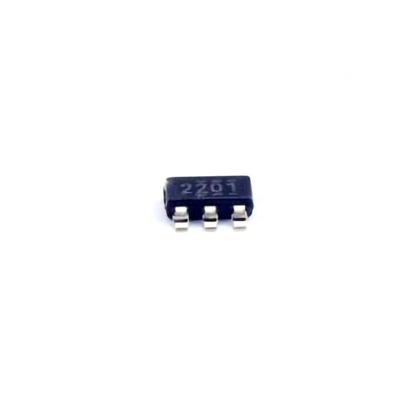
Understanding the TPS562201DDCR and Common Issues
The TPS562201DDCR is a robust and efficient step-down (buck) voltage regulator from Texas Instruments. With a wide input voltage range and adjustable output, this converter is ideal for Power ing various electronic devices, from microcontrollers to sensors. Despite its excellent specifications, users may encounter some common issues when integrating it into their designs or troubleshooting it in the field.
1. Insufficient Output Voltage
One of the most frequent issues encountered when using the TPS562201DDCR is an insufficient or unstable output voltage. This can cause the powered device to malfunction or fail to start. Several potential causes could contribute to this issue:
Potential Causes:
Incorrect Feedback Loop: The TPS562201DDCR uses a feedback loop to regulate its output voltage. If the feedback Resistors are incorrectly chosen or placed, the output voltage will be misregulated. Always ensure that the feedback resistors are connected correctly and that their values match the desired output voltage.
Faulty Capacitors : Inadequate input or output capacitor s can also lead to unstable output. Low ESR (Equivalent Series Resistance ) capacitors are recommended to maintain smooth voltage regulation.
Input Voltage Drop: A voltage drop at the input, possibly due to insufficient current capacity of the input power supply or long wires causing resistance, can cause the TPS562201DDCR to fail in maintaining a stable output.
Solution:
Double-check the feedback resistor values and their connection to the IC. Ensure the capacitors meet the recommended specifications in the datasheet (low ESR and high-quality ceramics are ideal).
Ensure that the input power supply can provide sufficient current for the TPS562201DDCR and check the input voltage against the recommended input range of the device.
Test the output under load to see if the voltage drops significantly, indicating that the converter is not able to supply enough current.
2. Overheating Issues
Overheating is another concern when using the TPS562201DDCR, especially in high-power applications or where the power dissipation is not adequately managed.
Potential Causes:
High Current Demand: The TPS562201DDCR is capable of delivering up to 2A of output current. However, if the load current exceeds this rating or the output voltage is set too high for the application, the IC may overheat due to excessive power dissipation.
Inadequate Heat Sinking: The IC may be mounted in an area with poor ventilation or without an adequate heat sink. In such conditions, the device may quickly reach its thermal shutdown limit.
Solution:
Always ensure that the load current is within the recommended limits (2A). For higher currents, consider using a converter with a higher current rating.
Improve airflow around the IC or use a heat sink if necessary. Additionally, verify that the PCB layout is optimized for thermal management, ensuring the IC's thermal pad is connected to a large copper area to dissipate heat effectively.
3. Noise and Ripple on the Output
Voltage ripple or high-frequency noise on the output can cause erratic behavior in sensitive downstream circuits, leading to performance degradation. Noise and ripple are particularly common in DC-DC converters like the TPS562201DDCR.
Potential Causes:
Poor PCB Layout: Inadequate layout can result in improper grounding or long, inductive traces, which can exacerbate ripple and noise.
Incorrect Capacitor Selection: Capacitors with poor high-frequency performance can fail to filter out ripple effectively, leading to noisy output.
Inadequate Output Filtering: If the output filter components (inductors and capacitors) are poorly chosen or incorrectly placed, they may not filter out switching noise properly.
Solution:
Optimize the PCB layout for noise reduction. Keep the feedback loop short and ensure that the input and output capacitors are placed as close as possible to the corresponding pins of the TPS562201DDCR.
Use high-quality ceramic capacitors with good high-frequency performance at both the input and output stages.
Consider adding additional filtering stages or using a ferrite bead to reduce high-frequency noise if necessary.
Advanced Troubleshooting Solutions and Tips
While the first part addressed some of the more common issues with the TPS562201DDCR, there are more advanced troubleshooting tips that can help you resolve deeper issues and optimize performance.
4. Startup Failures or Delayed Startup
A TPS562201DDCR that fails to start or has a delayed startup can be frustrating, especially if it disrupts the power-up sequence of your entire system. There are several potential reasons for this:
Potential Causes:
Incorrect Power-Up Sequence: The TPS562201DDCR requires a specific sequence of events to start properly. If the enable pin (EN) is not correctly tied to the logic level or if the input voltage rises too slowly, the IC may fail to start.
Faulty External Components: Sometimes, the problem lies in external components, such as the soft-start capacitor or resistors that control the timing of the IC’s startup.
Overcurrent or Short Circuit: A short circuit or excessive current draw on the output can prevent the TPS562201DDCR from starting up. The IC’s internal protection circuitry will stop the operation if these conditions occur.
Solution:
Check the voltage levels on the enable pin and ensure it is pulled high (typically 3.3V or 5V) to allow the IC to start.
Verify that the soft-start capacitor is properly sized according to the datasheet recommendations.
Ensure that there is no short circuit or excessive load on the output during startup. Use an oscilloscope to check for abnormal current spikes during startup.
5. Incorrect or Fluctuating Feedback Voltage
If you observe that the feedback voltage is incorrect or fluctuating, it can indicate an issue with the voltage regulation loop or feedback network.
Potential Causes:
Faulty Feedback Resistors: Incorrect resistor values or poor solder joints in the feedback loop can lead to improper feedback voltage, causing the output to be incorrect or unstable.
Poor Load Regulation: If the output voltage fluctuates significantly with varying load conditions, the TPS562201DDCR might not be able to maintain the set output voltage.
Solution:
Double-check the feedback resistors for accuracy and proper connection. Ensure that there is no corrosion or poor contact that could affect the feedback voltage.
Improve the PCB layout to reduce noise coupling into the feedback network.
Test the load regulation by applying varying loads and checking the output voltage for stability. If the voltage fluctuates significantly, consider adding additional bulk capacitors at the output.
6. Intermittent Operation or Complete Failure
Intermittent operation or total failure of the TPS562201DDCR can be one of the most difficult issues to diagnose.
Potential Causes:
Power Supply Instability: If the input supply to the TPS562201DDCR is unstable or noisy, it can cause the converter to behave unpredictably. Voltage dips, spikes, or high-frequency noise can trigger unwanted behavior.
Thermal Shutdown: The TPS562201DDCR has built-in thermal shutdown protection. If the temperature exceeds a certain threshold, it will shut down to prevent damage, and may not restart until it cools down.
Internal Damage or Faulty IC: In some rare cases, the IC itself may have become damaged due to excessive current, overvoltage, or improper handling during the soldering process.
Solution:
Check the stability of the input power supply. Use an oscilloscope to monitor the input voltage for any irregularities or spikes.
Ensure that the IC is not overheating. If the temperature is a concern, improve the thermal management and ventilation around the IC.
If the IC has been exposed to conditions outside the recommended specifications, such as excessive current, voltage, or improper soldering, it may be necessary to replace the IC.
Conclusion
The TPS562201DDCR is a highly efficient and versatile DC-DC converter, but like all power supply components, it requires careful design and troubleshooting to function optimally. By understanding the common issues, such as insufficient output voltage, overheating, noise, and startup failures, and applying the corresponding solutions, you can ensure reliable performance and avoid costly downtime in your projects. Always refer to the datasheet for the most accurate information, and ensure that your power supply, PCB layout, and component selection are all optimized to meet the demands of your application.
By following this guide, you’ll be well-equipped to tackle the most common challenges with the TPS562201DDCR and ensure its smooth operation in your electronic designs.
If you are looking for more information on commonly used Electronic Components Models or about Electronic Components Product Catalog datasheets, compile all purchasing and CAD information into one place.


