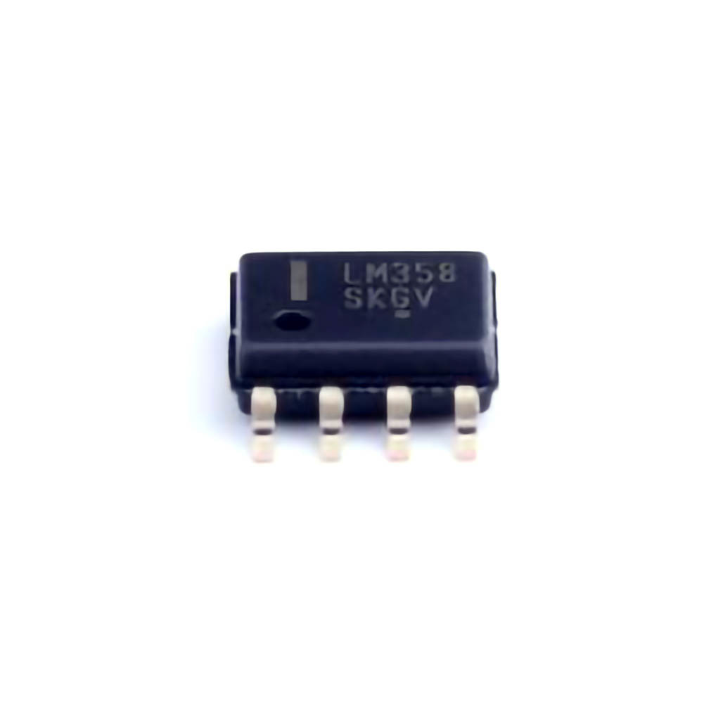
Understanding Common Issues with LM358DR2G Operational Amplifier
The LM358DR 2G is a popular dual-operational amplifier (op-amp) from ON Semiconductor, known for its versatility in various electronic circuits. As with any component, issues may arise during the design, testing, or deployment phases. Identifying and addressing these issues can significantly improve circuit reliability and performance. In this part of the article, we will cover some of the most common problems encountered with the LM358 DR2G op-amp and provide tips on how to troubleshoot them.
1. Incorrect Power Supply Voltages
One of the most frequent issues when working with the LM358 DR2G is incorrect power supply voltage. The LM358 DR2G has a single-supply voltage range between 3V and 32V (or dual-supply range of ±1.5V to ±16V). If the voltage supplied is either too low or too high, it can cause the op-amp to malfunction.
Symptoms:
Distorted output signals.
No output or erratic behavior.
Amplifier becomes hot or even burns out.
Solution:
Ensure that the power supply voltage matches the specifications outlined in the datasheet. For a single-supply setup, use voltages within the recommended range of 3V to 32V. If you are using a dual-supply, make sure the positive and negative voltages are balanced within the range of ±1.5V to ±16V. Use a multimeter to check the power rails before powering up the circuit.
2. Improper Grounding
Grounding is crucial for the stability and performance of the LM358D R2G op-amp. A poorly connected ground can result in noisy or unstable operation.
Symptoms:
Fluctuating or unstable output.
Incorrect voltage at the output stage.
Solution:
Ensure that the ground connection is solid and low-impedance. Use a star grounding technique where possible, and minimize the distance between the ground of the op-amp and other critical components. A noisy or floating ground can cause oscillations or other unexpected behavior. Additionally, avoid ground loops by keeping the ground planes separate in multi-layer PCB designs.
3. Incorrect Feedback Resistor Values
The LM358DR2G op-amp relies heavily on feedback resistors to define the gain and response of the amplifier. Using incorrect values for these resistors can result in improper amplification, distortion, or instability.
Symptoms:
Excessive or insufficient gain.
Amplification distortion or clipping.
Noisy or unstable output.
Solution:
Check that the feedback resistor values align with your design requirements. Use a multimeter to confirm the actual resistor values on the board. Incorrect resistor values can alter the expected gain or feedback path, which in turn impacts the output signal. If possible, simulate the circuit in SPICE before constructing it to verify the resistor values and the overall behavior of the op-amp.
4. Inadequate Decoupling Capacitors
Decoupling capacitor s are critical in filtering out noise and stabilizing the power supply to the LM358DR2G op-amp. Without proper decoupling, noise from other parts of the circuit or the power supply can affect the op-amp's performance.
Symptoms:
Increased noise or distortion in the output signal.
Unstable voltage at the power supply pins of the op-amp.
Solution:
Place appropriate decoupling capacitors (typically 100nF ceramic and 10uF electrolytic) as close as possible to the power supply pins of the LM358DR2G. This will help eliminate high-frequency noise and reduce the ripple from the power supply. Check the capacitors' placement and values to ensure they match the design specifications.
5. Overdriving the Input Voltage
The LM358DR2G is designed for use in a wide range of applications, but it has input voltage limitations. Applying voltages that exceed the op-amp’s input range can result in damage or improper operation.
Symptoms:
Clipping or distortion at the output.
Reduced linearity in amplification.
Solution:
Ensure that the input voltage does not exceed the supply voltage or fall below the ground reference by more than a specified amount (typically 0.3V below the negative supply rail or 0.3V above the positive supply rail). If necessary, use clamping diodes or series resistors to protect the input pins from excessive voltage swings.
Advanced Troubleshooting Techniques for the LM358DR2G
While the common issues discussed in Part 1 are relatively easy to diagnose, more advanced troubleshooting may be required for persistent or complex problems. In this part, we will explore advanced troubleshooting techniques and solutions that can help you resolve deeper issues with the LM358DR2G.
1. Identifying and Addressing Oscillations
Oscillations are one of the most challenging problems that engineers may encounter when working with op-amps like the LM358DR2G. These unwanted high-frequency oscillations can significantly affect circuit performance, causing erratic behavior or instability.
Symptoms:
High-frequency oscillations at the output.
A continuous sine or square wave signal at the output when it should be steady.
Increased power consumption.
Solution:
Oscillations are typically caused by improper compensation, feedback loops, or layout issues. To address this, check for any external capacitors that may be required for frequency compensation. Adding a small compensation capacitor (e.g., 10pF to 100pF) between the op-amp’s output and inverting input can often stabilize the circuit. Also, ensure that the feedback network is properly designed to prevent phase shifts that could cause instability.
2. Thermal Runaway and Overheating
The LM358DR2G is a low-power device, but like all op-amps, it can overheat if subjected to excessive current or power dissipation. Thermal runaway occurs when the op-amp’s temperature rises uncontrollably, leading to further increases in current and potentially catastrophic failure.
Symptoms:
The op-amp becomes excessively hot to the touch.
Erratic output behavior when the device heats up.
Possible damage to the op-amp or surrounding components.
Solution:
Check the operating conditions to ensure that the LM358DR2G is not being overdriven or forced to operate at high current levels. Use a heatsink or improve ventilation in the circuit if necessary. Consider reducing the supply voltage or using a current-limiting resistor to prevent excessive power dissipation. Additionally, ensure that the output is not shorted, which can cause excessive current draw and heat.
3. Input Bias Current Issues
Input bias current is the small current that flows into or out of the input terminals of the op-amp. While the LM358DR2G has relatively low input bias current, it can still cause problems in high-impedance circuits or when using high-value resistors in the input network.
Symptoms:
Offset voltage at the output.
Distortion or drift in the output signal.
Solution:
To mitigate input bias current effects, use a pair of resistors in the non-inverting and inverting input paths that are matched in value. This will balance the bias currents and prevent output drift. Alternatively, you can use a high-quality op-amp with lower bias current if your circuit demands very high accuracy.
4. Damaged or Faulty LM358DR2G
In some cases, the LM358DR2G itself may be faulty due to manufacturing defects, improper handling, or damage from ESD (electrostatic discharge) or overvoltage conditions.
Symptoms:
The op-amp does not function at all.
The output signal is stuck at a certain voltage.
Unusual heating or physical damage to the package.
Solution:
If you suspect the op-amp is damaged, replace it with a new unit. Always follow proper ESD precautions when handling sensitive components like op-amps. If you're working with a circuit where the LM358DR2G is exposed to harsh environments (e.g., high voltage spikes, temperature extremes), consider using more robust components or adding protection circuitry.
5. Probing the Circuit with an Oscilloscope
If you are still unable to diagnose the issue, an oscilloscope can be a valuable tool in identifying problems with the LM358DR2G. By probing the inputs and output of the op-amp, you can visualize the signals in real time and identify distortions, noise, or other anomalies.
Symptoms:
Unusual waveform shapes or distorted signals.
Unexpected behavior in the feedback network.
Solution:
Connect the oscilloscope probes to various points in the circuit: the non-inverting input, the inverting input, the output, and the power supply rails. Compare the actual waveform with the expected behavior based on the design. This should help you pinpoint where the problem is occurring and guide your troubleshooting efforts.
By following these troubleshooting strategies and solutions, you can ensure that the LM358DR2G performs optimally in your circuit. Whether dealing with power supply issues, oscillations, or thermal problems, this guide provides you with the tools needed to effectively diagnose and resolve common op-amp challenges.
Partnering with an electronic components supplier sets your team up for success, ensuring the design, production, and procurement processes are quality and error-free.


