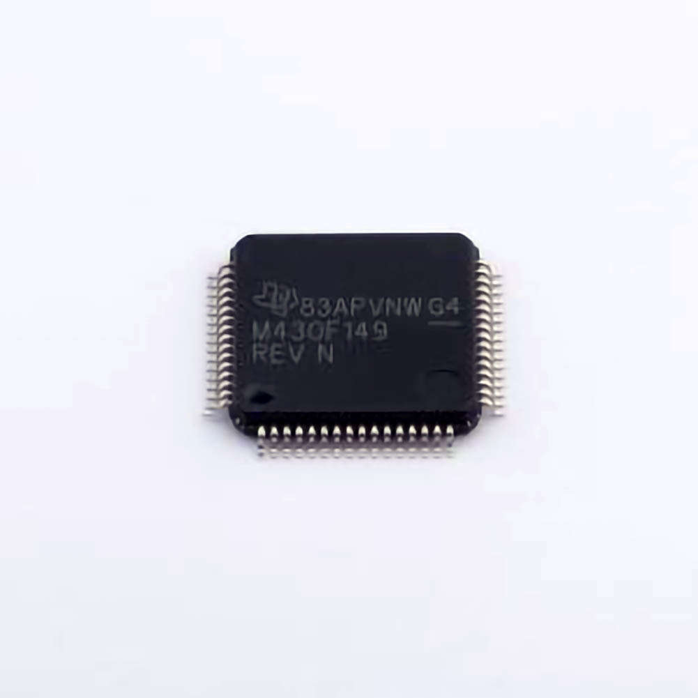
This article explores common troubleshooting issues faced by engineers and developers using the MSP430F149IPMR microcontroller. It provides insightful solutions and best practices to help optimize performance and resolve common problems. Whether you're dealing with Power issues, signal instability, or software bugs, this guide is your go-to resource for effective solutions.
Identifying and Resolving Power Issues
The MSP430F149IPMR, like any embedded system, can face power-related issues that affect its functionality. These problems often arise due to improper configuration, faulty power supply design, or incorrect voltage levels. In this section, we’ll focus on diagnosing and fixing the most common power-related challenges associated with the MSP430F149IPMR.
1.1 Insufficient Power Supply Voltage
The MSP430F149IPMR operates with a supply voltage of 2.2V to 3.6V. If the supply voltage falls outside this range, the microcontroller may fail to start or may exhibit erratic behavior. The key to resolving this issue is to check the voltage at the VCC pin with a multimeter and ensure that it is within the acceptable range.
Solution:
Verify Power Source: Ensure that the power supply is stable and within the recommended voltage range. If using a regulated power supply, check for any fluctuation or dips in the output voltage.
Capacitors and Filtering: To eliminate noise and maintain voltage stability, use appropriate decoupling capacitor s (0.1µF and 10µF) close to the VCC and GND pins. These will help filter out power noise and stabilize the supply.
1.2 Power Consumption During Low-Power Modes
The MSP430F149IPMR is designed to operate in ultra-low-power modes, but improper configuration of these modes can lead to unnecessary power consumption. Developers may inadvertently keep the microcontroller running in active mode when it should be in a low-power state.
Solution:
Check Low-Power Mode Configuration: Ensure that the microcontroller is correctly configured to enter low-power modes such as LPM0, LPM3, or LPM4. This is done by setting the appropriate bits in the control register (e.g., PMMCTL0).
Monitor Power Consumption: Use a power analyzer to monitor the current consumption during different operating modes. This can help pinpoint whether the device is drawing more power than necessary.
1.3 Brown-Out Reset (BOR) Issues
The MSP430F149IPMR has an integrated Brown-Out Reset (BOR) feature that resets the microcontroller if the supply voltage drops below a specified threshold. However, if the BOR threshold is set incorrectly, it may trigger false resets or fail to reset the device when the supply voltage drops too low.
Solution:
Check BOR Configuration: The BOR threshold can be adjusted via the PMMCTL0 register. Verify that it is set according to your system’s voltage levels.
Monitor Voltage Drops: Use an oscilloscope to observe the supply voltage. If there are any sudden drops below the threshold, it may trigger a reset that causes system instability.
1.4 Unstable Power Supply Due to Grounding Issues
A common source of power instability is poor grounding. If the ground connections are not solid or have high impedance, it can lead to fluctuating voltage levels, which in turn cause erratic behavior in the microcontroller.
Solution:
Improve Grounding: Ensure that the ground plane in the PCB design is continuous and has a low impedance. Minimize the distance between the ground pin of the MSP430F149IPMR and the power supply ground.
Use a Single-Point Ground: Avoid multiple ground paths that can create ground loops. A single-point ground is typically recommended for optimal performance.
Addressing Signal and Software Issues
Along with power-related challenges, developers using the MSP430F149IPMR may encounter issues related to signal integrity, peripherals, and software bugs. These issues can lead to unexpected behavior, system crashes, or incorrect readings from sensors. In this part, we’ll examine common signal and software issues and offer practical solutions.
2.1 Signal Integrity and I/O Problems
Signal integrity issues can manifest as noise or cross-talk between adjacent pins, leading to corrupted data or unreliable sensor readings. This is particularly true when working with analog inputs, serial Communication (e.g., UART, SPI), or other high-speed digital signals.
Solution:
Use Proper Routing Techniques: For high-speed signals, ensure proper trace routing on the PCB. Keep analog and digital traces separate, and avoid running high-speed traces close to each other to minimize interference.
Apply Termination Resistors : When working with high-speed serial protocols such as UART or SPI, consider using termination resistors to match impedance and reduce reflections.
Use Ground and Shielding: For sensitive analog signals, place ground traces around signal lines to act as shields, reducing noise and improving signal integrity.
2.2 Timer and Clock Issues
The MSP430F149IPMR is equipped with multiple timers that help manage time-sensitive operations. However, incorrect timer configuration can result in inaccurate timing, incorrect pulse generation, or failure to trigger interrupts as expected.
Solution:
Check Clock Source: Ensure that the clock source for the timers is correctly selected. The MSP430F149IPMR supports various clock sources such as the ACLK, MCLK, and SMCLK, which can be configured in the BCSCTL1 and BCSCTL2 registers.
Verify Timer Registers: Incorrectly configured timer registers can lead to problems with overflow, interrupts, or output behavior. Double-check the TACTL, TACCR0, and TACCTLx registers to ensure they are set correctly for your application.
2.3 Debugging Software Bugs
Software bugs can cause a wide range of issues, from system crashes to incorrect outputs. Debugging the MSP430F149IPMR requires a careful analysis of the firmware to identify logical errors, buffer overflows, or incorrect peripheral configurations.
Solution:
Use a Debugger: A hardware debugger, such as the MSP430 USB Debugger, can be used to step through your code, set breakpoints, and inspect register values in real-time. This allows you to quickly identify issues in the firmware.
Check Stack Overflow: Ensure that the stack is large enough to accommodate function calls and local variables. An overflow can corrupt memory, leading to unexpected crashes or behavior.
Utilize Watchdog Timer: The watchdog timer (WDT) can help reset the system in case of an unresponsive software state. Ensure that it is properly configured to avoid unintended resets or system hangs.
2.4 Peripheral Configuration Issues
The MSP430F149IPMR is equipped with a variety of peripherals, such as ADCs, DACs, UART, and I2C. Incorrect configuration of these peripherals can lead to faulty data acquisition, failed communication, or failure to operate as expected.
Solution:
Double-Check Peripheral Settings: Verify the configuration of each peripheral by checking the relevant registers (e.g., ADCCTL1, UCA0CTL1, P1DIR, etc.). Ensure that the correct pins are assigned and the correct communication protocol is selected.
Test Peripherals Individually: When debugging peripheral-related issues, it’s helpful to test each peripheral in isolation. For example, use the ADC to take a known input (like a voltage reference) to ensure it’s reading correctly.
2.5 Communication Failures (UART, SPI, I2C)
Communication failures, such as missed bytes, incorrect data, or no data transmission at all, can be caused by several factors, including incorrect baud rates, improper pin connections, or incorrect peripheral initialization.
Solution:
Verify Baud Rate and Clock Settings: Ensure that the baud rate for UART or SPI communication matches the configuration on both the MSP430F149IPMR and the connected device. Also, verify that the clock source and baud rate registers are correctly configured.
Check Pin Connections: Confirm that the correct pins are used for TX/RX (UART), MISO/MOSI (SPI), or SDA/SCL (I2C). Check for shorts, open circuits, or incorrectly wired connections that may disrupt communication.
Enable Pull-up/Pull-down Resistors: Some I2C and SPI lines may require pull-up or pull-down resistors to ensure proper voltage levels on the lines.
Conclusion
The MSP430F149IPMR is a versatile and powerful microcontroller, but like any embedded system, it is prone to a range of issues, including power-related challenges, signal integrity problems, and software bugs. By following the troubleshooting steps and solutions outlined in this article, developers can effectively identify and resolve common problems, ensuring smooth and reliable system operation. Whether dealing with power issues, timer misconfigurations, or communication failures, these practical tips will help keep your MSP430F149IPMR project on track and performing at its best.
If you are looking for more information on commonly used Electronic Components Models or about Electronic Components Product Catalog datasheets, compile all purchasing and CAD information into one place.

