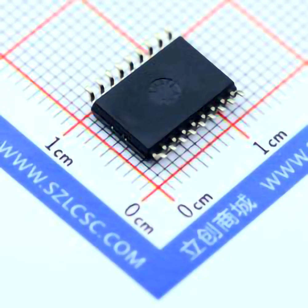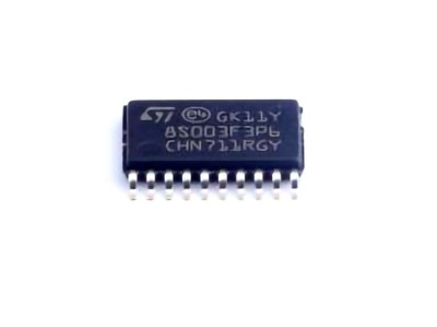
The ULN2803ADW R is a widely used octal Darlington transistor array that serves as a critical component in various electronic systems. This guide will provide a detai LED troubleshooting approach to diagnosing and solving common issues faced when using this component. Learn about potential failures, their causes, and practical solutions for better performance and reliability.
Understanding the ULN2803A DWR and Common Issues
The ULN2803ADWR is an octal Darlington transistor array that is frequently used in applications requiring high-voltage and high-current driving capabilities. It's widely employed in interfacing low-voltage control systems with high-power loads, such as relays, motors, and lamps. As with any electronic component, it can experience various issues over time or during initial setup. Understanding these problems and knowing how to troubleshoot them is crucial for ensuring the reliable performance of your system.
What is the ULN2803ADWR?
Before delving into troubleshooting, it's essential to understand the function and characteristics of the ULN2803ADWR. This device contains eight Darlington pairs, which are typically used for driving high-current loads. Each output is capable of handling up to 500mA of continuous current, with a peak current rating of 600mA. The ULN2803 is commonly used in control circuits for driving motors, relays, LED s, and other actuators that require higher currents than microcontrollers or logic circuits can supply.
The device operates by taking input signals (from low-power logic devices) and amplifying them through the Darlington transistor pairs. This allows it to drive larger loads without overloading the controller. The ULN2803ADWR also includes flyback diodes to protect against voltage spikes generated by inductive loads.
Common Issues with the ULN2803ADWR
Overheating
One of the most common issues with the ULN2803ADWR is overheating. When the device is subjected to excessive current, it can become hot to the touch, leading to potential failure. Overheating may be caused by various factors, including improper current limiting, incorrect voltage levels, or inadequate heat dissipation.
Possible Causes:
High current draw: Exceeding the 500mA per channel can cause excessive heat.
Inadequate heat sinking or airflow: If the chip is not properly ventilated, it can overheat.
Incorrect resistor values: Misplaced resistors in series with the load could lead to higher-than-expected current flow through the Darlington transistors.
Solution:
Ensure that the current requirements of the load do not exceed the maximum current rating of the device.
Add heat sinks or improve ventilation in the circuit to allow for better heat dissipation.
Double-check the resistor values in your circuit to ensure that the current is being properly limited.
Failure to Drive Loads
If the ULN2803ADWR is not driving the connected loads as expected, there could be several reasons behind this issue. It could be due to a damaged input, poor signal quality, or issues with the transistors themselves.
Possible Causes:
Incorrect logic levels: The device might not be receiving the correct high or low signal at the input.
Input pins floating: Floating input pins can cause erratic behavior, including failure to drive loads.
Faulty Darlington pairs: If the Darlington pairs inside the ULN2803 are damaged, they may not be able to switch properly.
Solution:
Verify that the input signal is within the required logic level range for the ULN2803ADWR.
Use pull-down resistors on the inputs to prevent floating inputs, which can lead to unpredictable operation.
Test the ULN2803ADWR with known working components to determine if the issue lies within the device itself.
Voltage Spikes and Inductive Load Issues
The ULN2803ADWR is designed with flyback diodes to protect the transistors from voltage spikes caused by inductive loads, such as motors and relays. However, excessive or high-frequency spikes can still cause problems, especially if the diodes are damaged or ineffective.
Possible Causes:
Inductive load without proper diode protection: If the flyback diodes are not functioning correctly, voltage spikes from inductive loads can damage the transistors.
Incorrect load configuration: If the load is incorrectly wired or mismatched, it can cause excessive back-emf (electromotive force).
Solution:
Always ensure that the flyback diodes are intact and functioning correctly when driving inductive loads.
For particularly high-voltage inductive loads, consider adding external diodes for additional protection.
Check the load wiring to ensure that it matches the specifications outlined in the datasheet.
Signal Integrity and Noise
When using the ULN2803ADWR in high-speed circuits, noise and signal integrity issues may arise, especially when driving long cables or high-power loads. Poor signal quality can lead to the transistors failing to turn on or off properly, causing erratic behavior.
Possible Causes:
EMI (Electromagnetic Interference) affecting the input signals.
Long wiring between the control circuit and the ULN2803, leading to voltage drops or noisy signals.
Lack of proper decoupling capacitor s.
Solution:
Implement proper decoupling capacitors close to the device to filter noise and improve signal integrity.
Use shielded cables and minimize the length of wiring between the controller and the ULN2803.
Consider adding a low-pass filter to reduce high-frequency noise from the input signals.
Grounding Issues
Grounding is crucial for the ULN2803ADWR to function correctly. Improper grounding can lead to unexpected behavior, including failure to drive loads or incorrect logic levels at the inputs.
Possible Causes:
Shared ground with noisy power sources or high-power devices can lead to fluctuating ground levels.
Floating grounds or poor connections can create ground loops, resulting in unstable operation.
Solution:
Ensure that the ULN2803ADWR has a solid, stable ground connection that is separate from noisy power sources.
Use star grounding techniques to prevent ground loops and minimize voltage differences between components.
Advanced Troubleshooting and Preventative Solutions
Once the common issues and their respective solutions have been addressed, it's essential to dive deeper into more advanced troubleshooting strategies and preventative measures. These techniques can help you not only fix immediate problems but also reduce the likelihood of recurring failures in the future.
Advanced Troubleshooting: Analyzing Faulty Components
When dealing with an apparently malfunctioning ULN2803ADWR, it’s crucial to perform a thorough analysis of the surrounding components and the environment in which the IC operates. Simple fixes like replacing a faulty resistor or adding a heatsink might not always be enough. In some cases, it could be the overall circuit design that needs optimization.
Test the Darlington Transistors Individually
One of the advanced troubleshooting techniques is to test each of the eight Darlington pairs inside the ULN2803ADWR individually. Using a multimeter in diode-testing mode, you can check each transistor for shorts or open circuits. By analyzing each transistor's base-emitter and collector-emitter junctions, you can identify potential faults within the IC.
Solution:
If a transistor is found to be defective, the ULN2803ADWR will likely need to be replaced, as repairing individual components within the IC is not practical.
Check for Short Circuits or Overload Conditions
A short circuit or an overloaded output could be causing your ULN2803ADWR to fail. This is especially true when dealing with high-current loads like motors or solenoids. An overload condition might cause excessive heat or damage to the transistor pairs.
Solution:
Use a current-limited power supply during testing to prevent overloading the ULN2803ADWR.
Inspect the circuit for potential shorts, particularly at the output connections, and verify that there are no connections causing a direct path between the output and ground.
Thermal Imaging and Heat Mapping
If you're still unable to pinpoint the issue, a thermal imager or infrared thermometer can be a valuable tool. This allows you to visually inspect the temperature distribution across the ULN2803ADWR, identifying areas that are abnormally hot, which could indicate a fault in a specific channel or transistor.
Solution:
Use thermal imaging to detect overheating areas. If you find a hot spot, investigate the specific output or transistor causing the issue. This method is especially useful for identifying localized failures that might not be obvious from visual inspection.
Preventative Solutions: Improving Longevity and Reliability
To avoid encountering frequent issues with the ULN2803ADWR, it's essential to adopt preventative strategies that enhance the longevity and reliability of the component. Here are some key measures to implement in your circuit design:
Proper Sizing of Components
One of the best ways to avoid future issues is to ensure that all components in your circuit are correctly sized for the expected load. This includes resistors, capacitors, and the ULN2803ADWR itself. Overloading any part of the circuit, including the IC, can lead to premature failure.
Solution:
Refer to the datasheet for recommended operating conditions and design your circuit to stay within those parameters.
Use resistors with a higher power rating than the expected current and ensure that the load’s current doesn’t exceed the ULN2803’s maximum rating.
Use of External Protection
While the ULN2803ADWR has built-in flyback diodes, it may be beneficial to add additional protection, especially for circuits dealing with high-energy inductive loads. This could include using external diodes, transient voltage suppressors ( TVS ), or snubber circuits.
Solution:
For high-current applications, consider adding external diodes or other protection circuits to further safeguard the ULN2803ADWR against voltage spikes and transients.
Regular Maintenance and Inspection
Even with the best design practices, components can degrade over time. Regular maintenance and inspection are essential for ensuring the long-term reliability of your circuit.
Solution:
Periodically inspect your system for any signs of wear, especially on high-stress components like the ULN2803ADWR. Look for signs of heat damage, discoloration, or visible wear and tear.
By understanding the common issues and applying these troubleshooting techniques and preventative solutions, you can significantly improve the reliability and longevity of your ULN2803ADWR-based systems. Whether you're designing new circuits or maintaining existing ones, these insights will help you optimize performance and minimize downtime.
If you are looking for more information on commonly used Electronic Components Models or about Electronic Components Product Catalog datasheets, compile all purchasing and CAD information into one place.


